Power Tip 37: Trade AC-line range for input-capacitor ripple current
Editor’s note: to see a linked list of all entries in the Power Tips series, click here.)
An interesting tradeoff occurs when you select the input filter capacitor in a low-power, offline power supply. You trade the ripple-current rating of the capacitor for the voltage range over which the supply needs to operate. By increasing the input capacitor, you apply more ripple current in it and narrow the operating input voltage range of the power supply by decreasing the droop in the input capacitor.
This impacts the transformer turns ratio and various voltage and current stresses within the power supply. A larger capacitor ripple current rating means less stress and a more efficient power supply.
Figure 1 and Figure 2 present two rectifier configurations used in offline power supplies. Figure 1 is a full-wave bridge, where the AC input voltage is simply rectified and fed to a capacitor. This type of circuit is popular in wide-range AC and 230-volt AC applications. The capacitor charges to the peak of the sine wave and is discharged for the majority of the half-period.
There are two components to the ripple current in the capacitor. The first is the charge period, where the current is set by the value of the capacitor and the applied dV/dt. The second is the discharge of the capacitor.
Power supplies act as constant-power loads, so the capacitor discharges at a non-linear rate and can be calculated as a change in energy:
W = ½ × C × V2 = P × dt.

Figure 1: Full-wave bridge is used in many offline designs.
Figure 2 illustrates a voltage doubler rectifier configuration which is used in many 115/230 VAC applications. If you have a 230 VAC application, your input stage needs to handle voltages as high as the maximum input voltage (265 VAC) times the crest factor, or nearly 400 volts.
The voltage doubler, when used with a 115 VAC input, boosts the rectified voltage to near the level of the 230 VAC input. The power supply then can be designed for only the 230 VAC line, reducing the rectified voltage range over which the power supply operates.
Switching between rectifier configurations is usually done with a jumper or switch. The only downside to this approach is that occasionally someone doubles a 230 VAC input and wreaks havoc with the power supply.
Figure 2 also shows some of the waveforms within the doubler circuit. The neutral is connected between capacitors. Two rectifiers apply the input voltage to each capacitor alternately. Each capacitor is charged to the peak line voltage once a cycle, so they each have a line-frequency ripple component. Since the capacitors are charged out-of-phase, the ripple frequency from their sum is twice the line frequency.

Figure 2: A voltage doubler reduces power-supply line range.
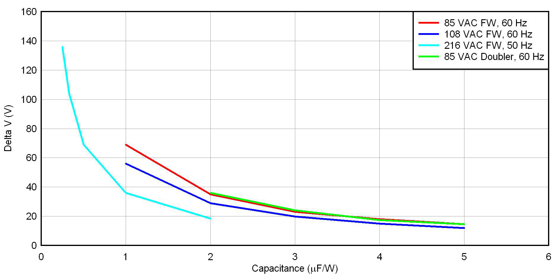
Figure 3 provides voltage droop normalized by μF/W for four rectifier/input voltage options. There are three full-wave bridge options for low-line US (108 VAC/60 Hz), low-line Japan (85 VAC/50 Hz) and low-line European (216 VAC/50 Hz) mains. There is also a doubler with low-line Japan.
For the full-wave bridge, the normalization is simply capacitance divided by power. In the doubler, the normalization is the capacitance of one of the two series connected capacitors, divided by the power.
To use this chart, determine your rectifier configuration and decide an acceptable voltage droop. Then you can simply read off the μF/W of the input capacitor. Finally, un-normalize this number by multiplying by your power.

Figure 3: A large capacitor reduces input-line range and improves efficiency.
You can then use Figure 4 to calculate the ripple-current rating of the capacitor. Figure 4 shows normalized ripple current versus normalized input capacitance.
It is interesting to note that the ripple current is not a strong function of the capacitance. This is because during the discharge, the current is set by an almost-constant draw from the load. Only during charge cycles are the currents much different.
This is seen in the gradual ripple current increase as the capacitance (μF/W) is increased. This comes from the higher peak currents, with reduced conduction angles with larger capacitance. Note: the chart only includes line-frequency ripple currents and does not include the effects of the high-frequency power supply ripple current.

Figure 4: Increasing μF/W does not significantly increase input-capacitor ripple current.
To summarize, the designer has a significant tradeoff in picking the input capacitor and rectifier configuration. If a full-wave bridge in a wide-range application is chosen, the supply may need to run over a 4:1 input range. If the designer chooses to incorporate a voltage doubler in the design to reduce the range, the potential exists for overvoltages from customer error.
The designer can somewhat limit operating range by proper choice of the input capacitor, based on the charts in this paper.
Please join us next month when we will discuss an inexpensive latch circuit for power supply protection.
For more information about this and other power solutions, visit: www.ti.com/power-ca.
About the author
 Robert Kollman is a Senior Applications Manager and Distinguished Member of Technical Staff at Texas Instruments. He has more than 30 years of experience in the power electronics business and has designed magnetics for power electronics ranging from sub-watt to sub-megawatt with operating frequencies into the megahertz range. Robert earned a BSEE from Texas A&M University, and a MSEE from Southern Methodist University.
  If you enjoyed this article, you will like the following ones: don't miss them by subscribing to :
eeNews on Google News


