Breaking the 100A barrier in POL converters requires fresh thinking
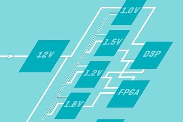
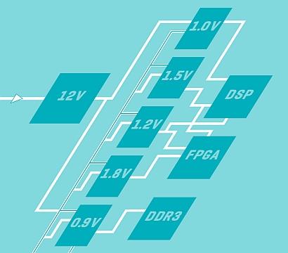
Over the past two decades, the electronics industry has seen the supply voltage for high-density logic and processors drop from an average of 5V to 1V or less. At the same time, power envelopes for server-class equipment, which are generally thermally limited, are still potentially 100W or more. The result is a current demand that is beginning to exceed the 100A level at the point of load (POL), a shift that challenges conventional power-conversion architectures.
Scaling down voltage while current scales up has major implications for efficiency. Conduction-related losses are proportional to the square of the output current (I2out), with the inductors and power transistors being major contributors. Switching incurs higher-than-expected losses. During switching transitions, the control switch has a switching loss proportional to a combination of the output current, the difference between the input and output voltage of the converter, and the duration of the switching transition. These factors tend to point to the use of lower switching frequencies, which means devoting more space to the POL converters and passive support components such as inductors and decoupling capacitors, which is not an acceptable change.
System design vs. marketing requirements
In many of these advanced systems, the available PCB space is not increasing but reducing, which places much higher pressure on designers who may not be power specialists. Engineers working with advanced processors and programmable logic devices also have to cope with late changes to specifications, putting even more pressure on the POL design. The initial data sheet may not reflect the voltage and energy demands of the final production chip, which can lead to a sub-optimal power delivery architecture using traditional analog converter technology.
By improving topologies and approaches, it is possible to overcome some of the efficiency and space issues that face high-current power-conversion designs. One possibility is to be more flexible with the way that the converter uses space within the system. The natural answer is to design converters that trade board area for height, and it is possible to provide far greater flexibility to the space-conscious board designer by exploring the X, Y, and Z axes, depending on the space limitations. But there are also possibilities for new circuit topologies, especially as existing topologies have already reached their limits.
Various improvements in device Rds(on), switching characteristics and drive mechanisms have pushed the efficiency envelope for conventional buck converters almost to their limits. Large improvements through traditional design techniques are almost impossible to achieve. To deal with low voltages and high currents, a fresh look at the buck converter is needed.
The SEPIC-fed buck converter
This has been addressed through the creation of a SEPIC-fed buck (SFB) topology called Solus Power Topology. Importantly, this approach retains the simplicity and low cost of the synchronous buck converter yet improves power conversion efficiency and transient response.

To overcome the issue of I2outR losses in the buck converter, multiple energy delivery paths are used in the SFB topology to split the load current. This has the result of cutting conduction losses by the square of the current reduction. The use of multiple-current paths reduces the voltage stress on components by almost 50%. As a result, the topology can use lower-voltage MOSFETs and capacitors than can a standard buck converter design. Because lower-voltage devices tend to exhibit higher conductivity, conduction losses can be reduced compared to those possible with higher Rds(on) values needed for conventional buck-converter designs.
The pressure to deliver energy efficiency from these high-current, low-voltage systems means that the processors and support logic needs to move into lower-power modes frequently. But they need to restore full capability extremely quickly without suffering from voltage overshoots. An overshoot of just 2% can lead to a temporary shutdown that means a web search or VoIP connection fails, costing the service provider potential revenue. Transient response coupled with accurate power delivery is, therefore, vital.

Ch1 (blue): Vout, 10mV/div.; Ch2 (black): Iout, 10A/div
By analyzing the SEPIC-fed buck converter, it can be noted that the split current in the inductors would improve transient response: The load current through its integrated inductors for each stage is virtually halved, and this means it can also rise almost twice as fast. And, changes in the applied voltage allow the current to ramp down almost four times faster using a SEPIC-fed buck architecture than using a buck converter, when the switch is turned off.
Optimization
Users of advanced logic devices also have to deal with late changes to specifications. The initial data sheet may not reflect the voltage and energy demands of the final production chip, which can lead to a sub-optimal power delivery architecture using traditional analog converter technology.
Through the use of cutting-edge dual-phase digital control circuits (see Intersil’s ChargeMode technology as used on its ZL8800 PWM controller, for example) it is possible to implement much more advanced compensation and control functions that are reactive to sudden changes yet still efficient. This means large changes can be made to the response characteristics of the circuit without risk of damaging components or the circuit board.
Summary
The industry is now in a position where high currents need to be delivered to very delicate circuitry in small enclosures. Legacy topologies simply aren’t geared to doing this. Exceeding 100A will demand many new strategies, including the development of new topologies, new control strategies, and even new physical orientations if the challenge of high-current POL power delivery is to be met.
 If you enjoyed this article, you will like the following ones: don't miss them by subscribing to :