USB battery charging rev. 1.2: Important role of charger detectors
The USB Specification Evolves
Other than generous helpings of coffee, what helps industry decrease time to market, drive down cost, and focus more of the design cycle on innovation? Hint: standardization. By defining protocols and operating characteristics, standards have impacted all aspects of technology: device package sizes, pin outs, data and communication interfaces, software drivers, connectors, ESD ratings, environmental compliance, test fixtures. The list goes on and on. The more detailed a specification, the better equipped are developers for defining products that serve the marketplace. If there is any doubt about the value of tightly defined standards, go into any two clothing stores and buy the same size shirt.
The best standards grow with technology. Standards consider and then reflect the increasing complexity of an industry, while maintaining support for already established practices. The USB port is an excellent example of a versatile standard. Originally intended to standardize the connectors on a host computer, the USB specification advanced to allow “On the Go” (USB OTG) electronics to act as either the host or peripheral device.
The specification evolved again with the introduction of the USB Battery Charging Specification1 to account for the incredible boom of cell phones and other portable devices with a USB port. The USB standard is currently undergoing another evolution with the new USB3.1 specification and the innovative, symmetrical Type-C connector. Because of their ability to “keep up with the Joneses,”2 USB ports are now found wherever chargeable devices are found – which is everywhere.
The maintenance of a strong standard such as USB can even influence governmental policy. In June of 2009, the European Commission issued a memo intending to mandate a common charger for every data-enabled mobile phone that uses the Micro-USB connector and draws largely on BC1.2.3 In response, a memorandum of understanding (MoU) was signed by major mobile phone manufacturers including Apple, LG, Samsung, and Sony Ericsson, among others.4
The GSM Association, which organizes the Mobile World Congress and spans more than 220 countries, also announced intentions to standardize mobile phone charger connections with a USB connector.5 Both the Korean Telecommunications Technology Association and Chinese Ministry of Industry and Information Technology have released technical requirements for the standardization of mobile phone charging.6
Even the International Telecommunication Union, a specialized agency within the United Nations, published ITU-T L.1000, its recommendation to adopt a universal charger based on requirements from the GSMA, EU, and Chinese proposals.7 With the updated power-delivery provisions added to USB2.0, the introduction of USB3.1 in 2013, and the new Type-C connector in 2014, the adoption of a standard connector will continue to be influenced heavily by USB standards.
Charger Detection and Ports in BC1.2
Why are standards committees and governing bodies choosing to standardize around USB connectors and the protocols outlined in BC1.2? Establishing a common standard allows interoperability, optimal performance, and safety among any devices using USB. The specification defines how much power can be supplied by any port, as well as a smart way for portable devices to detect how much power can be drawn. Thus, any portable equipment manufacturer can design their product to be compatible with as many USB ports as possible.
Manufacturers will know how best to utilize each USB port and can anticipate what voltages and currents will be applied by the USB port. Given this knowledge, they can design without the risk of electrical overstress. Finally, the increasing the amount of charging current that a device can use significantly reduces the total charge time required. Consequently, charger detection is an important feature that should be built into all rechargeable devices that incorporate a USB port.
Before discussing the charger detection protocol, it is important to know the differences among available USB ports. A downstream port supports USB 2.0 communication, and a charging port can deliver currents larger than 500mA. The BC1.2 outlines three different port types: a standard downstream port (SDP), dedicated charging port (DCP), and charging downstream port (CDP).
Think of the SDP as the classic USB port. In addition to USB communication, it provides 100mA of current to peripheral devices when connected; the 100mA is negotiable up to 500mA. While most ports typically do not enforce this current limit, higher currents are not guaranteed. A DCP does not support USB communication, but can supply charge currents beyond 500mA without any negotiation.
A CDP supports both USB communication and high-current charging; it features internal circuitry that is switched on during the charger detection phase. Some electronics manufacturers build proprietary charger identification schemes in addition to the USB port types outlined in the specification. Those various schemes add another layer of charger detection technology that cannot be overlooked.
The Charger Detection Process

Figure 1. USB connector pins and data contact detection (DCD).
The charger detection phase outlined in BC1.2 has five basic steps.
- VBUS detection To ensure proper sequencing for any potential devices connected to a USB port, the VBUS and GND pins on the connector are intentionally made longer than the D+ and D- pins. This ensures that they make contact first (see Figure 1). Thus, before any detection can occur, the device must first sense that VBUS is present.
- Data contact detection (DCD) Once the voltage on VBUS is valid, the portable device must ensure that the data pins also make contact before any detection can occur. The end device might incorrectly identify what charger is present if it makes a premature decision before the data pins make contact.To perform DCD, the peripheral device must enable a 7µA to 13μA current source (referenced to +3.3V) on D+ and monitor its voltage. This current range is chosen to maintain proper logic levels across all voltage and resistance tolerances allowed in the specification. If D+ is open, the voltage will be logic high. If closed, D+ will read logic low regardless of the port type. If no data pin contact is sensed after the 1-second timeout period, the end device assumes that an SDP is present.
- Primary charger detection In this step, the end device differentiates the > 500mA-capable ports with the charging label (CDP and DCP) from the < 500mA port type (SDP). After disabling the current source from the DCD phase, the end device must then enable a 0.5V to 0.7V voltage source on D+ and a 25μA to 175μA current sink on D-. If a DCP or CDP is present, the 0.5V to 0.7V level will appear on D-. If a SDP is present, the voltage on D- will drop to zero. The end device switches in a comparator that compares D- to 0.25V to 0.4V. If the D- voltage is above 0.4V but less than the logic-low threshold of 0.8V, then the end device concludes that a charging port is present.
- Secondary charger detection After turning off the voltage source and current sink from the previous step, the end device needs to discern a CDP from DCP. To accomplish this, it performs the previous test in reverse. Thus a 0.5V to 0.7V voltage source is enabled on D-, and a 50μA current sink is enabled on D+. If a DCP is present, the 0.5V to 0.7V test voltage will appear on D+. If a CDP is present, the voltage on D+ will be zero.
- CDP charge current limit Since a CDP supports both data and high-current charging, one last distinction must be made. Because of the large amount of current in the USB cable, the host ground and device ground can only tolerate a ground offset of 375mV.

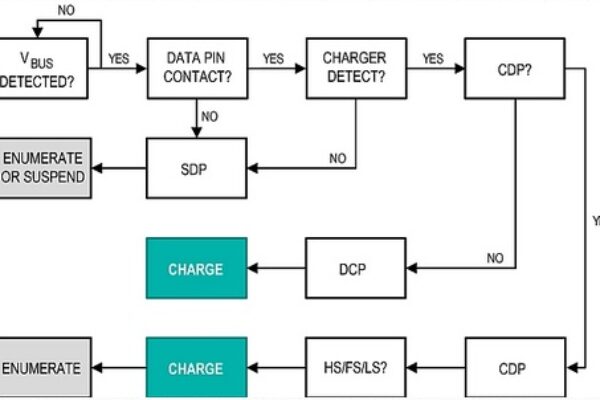
Figure 2. Summary of BC1.2 charger detection procedure.
While non-BC1.2-compliant chargers differ among manufacturers, many of these proprietary chargers identify themselves to end devices by the voltage level set by a resistive-divider between VBUS and ground. Depending on the level of coverage required by a charger detecting circuit, sensing circuitry can be added to detect the voltage levels on D+ and D- and, thus, to identify different manufacturer-specific chargers.
Charger Detection Technology
A USB charger detection IC is a single chip that implements many of the features and intricacies associated with BC1.2 charger detection. It is, admittedly, possible to implement the detection scheme discretely. But the number of components, board space, and time spent getting the discrete system to operate successfully would increase dramatically.
Adding a dedicated charger detection chip requires some additional board space, so manufacturers often combine other necessary or desirable features into the same package. Consequently, charger detection ICs are highly integrated with a myriad of additional features such as built-in switches for USB or UART/audio operation, serial control interfaces, overvoltage protection (OVP), USB OTG support, Li+ battery charging capability, or even the ability to perform USB enumeration.
Designers looking for a charger detector to drop into existing designs with minimal additional component count and board space will want the MAX14576/MAX14636/MAX14637 family of devices. This class of charger detector is powered directly from the USB VBUS line, so there is no need to add an additional supply. They feature internal SPST switches that are open when performing charger detection and closed when USB data communication is enabled.
Each device has an open-drain I/O to signal whether charging is allowed and the status of the data switches. Some charger detector versions have built-in Apple® charger detection in addition to the BC1.2 compliant port detection. Figure 3 shows an example detection circuit that handles the detection protocol. Fewer main processor resources are required and no major modifications need to be made to an existing design.
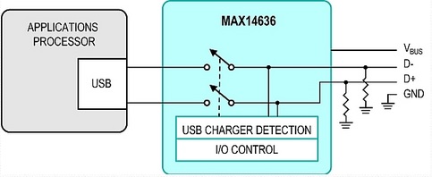
Figure 3. MAX14636 charger detector block diagram.
Over the last few years, smartphones took the world by storm. One of the major forces driving this sleek technology is form factor. As the list of features continues to increase while overall sizes are shrinking, careful planning and integrated solutions must be implemented to achieve the target shrinking specifications. Take, for example, a mobile phone that uses a single connector for charging; connecting to a PC; connecting to external accessories; or audio playback. To accomplish all of these tasks in a compact manner, system designers can opt to use a charger detection IC such as the MAX14656 (Figure 4).

Figure 4. A smartphone application using the MAX14656 charger detector.
This universal charger detection circuitry automatically distinguishes between different BC1.2-compliant ports and supports detection of most of the Apple proprietary chargers (e.g., 500mA, 1A, 2.1A). This device also has integrated DPDT switches, which allows the D+ and D- lines to be shared by a Hi-Speed USB transceiver, audio outputs, or even an internal UART. Using an I2C interface, the embedded processor reads whether a charger has been attached and configures the internal switches for the appropriate mode. When you consider the built-in OVP on the VBUS pin, the ESD protection on the data lines, and the 1.65mm x 1.65mm footprint, this single charger detector adds considerable versatility in a single connector for space-constrained designs.
The Promise for Portable Electronic Devices
Charger detection technology is so versatile because the basic charger detector functions can be coupled with a variety of other features to provide highly integrated circuits for manufacturers of portable electronics. Other solutions combine charger detection with Li+ battery-charging control in a single package. Some combine charger detection with USB self-enumeration. Today’s newest charger detector chips autonomously monitor the battery charge cycle in accordance with BC1.2, instead of tasking the embedded processor with manually adjusting the total current drawn for the time periods defined in the specification.
When you combine the charger detection and battery charging functions, you have smart battery switch control. This technology automatically switches from battery power to charger power when a charger is present. Consequently, some charger detector chips can both charge a battery and provide full-load current. Devices that do this also support thermal current regulation, which protects against dangerously high temperatures that result from simultaneously charging the battery and providing current to the load. By integrating charger detection and battery charging, the system designer can focus more on the end application and worry less about charging concerns.
Meanwhile, the USB BC1.2 specification continues to drive the electronics industry by providing a standard on which manufacturers can build upon. The large number of BC1.2-compliant chargers available today is only expected to multiply in volume. That fact alone makes incorporating a USB connector into a portable device an attractive option. With the use of charger detection ICs, the USB connector on a portable device becomes a versatile component. The built-in BC1.2 compliance keeps the implementation clean and simple to use. Whether designing a compact and portable product, the wealth of features accompanying charger detection ICs make them an extremely attractive integrated circuit.
Endnotes
1. This specification is identified now as BC1.2; see https://www.usb.org/developers/docs/devclass_docs/ )
2. The phrase, “keeping up with the Joneses,” is an American English idiom. For some background on the history and evolving meaning of the phrase, see the Wikipedia entry at https://en.wikipedia.org/wiki/Keeping_up_with_the_Joneses . Also The Phrase Finder at https://www.phrases.org.uk/meanings/216400.html .
3. See https://europa.eu/rapid/press-release_MEMO-09-301_en.htm.
4. See https://www.usb.org/press/USB-IF_Press_Releases/CENELEC_USB-IF.PDF.
Also https://europa.eu/rapid/press-release_MEMO-09-301_en.htm.
6. See China Communications Standards Association, "Technical Requirements and Test Method of Charger and Interface for Mobile Telecommunication Terminal Equipment" (CCSA YD/T 1591–2006, later updated to YD/T 1591–2009). Also Telecommunications Technology Association of South Korea, "Standard on I/O Connection Interface of Digital Cellular Phone" TTAS.KO-06.0028 released in March 2001. Later updated in 2002 (/R2), and in 2007 (/R4).
7. "Press Release: Universal phone charger standard approved—One-size-fits-all solution will dramatically cut waste and GHG emissions". Itu.int. 22 October 2009. Retrieved 4 November 2009, at https://www.itu.int/newsroom/press_releases/2009/49.html.
Apple is a registered trademark of Apple Inc.
 If you enjoyed this article, you will like the following ones: don't miss them by subscribing to :