RF and microwave solid-state power amplifiers design requires specialised engineering
The RF and microwave design software we use has removed much of the risk and guess work from creating a new amplifier design. For us, the software design tools have transformed the process of designing an amplifier in terms of speed, substantially shortening the product design cycle and massively improving the probability that the new device will perform as specified at the first attempt.
In the last 10 years or so wide bandgap transistors (SiC MESFETs and GaN HEMTs) have appeared on the market for high power RF/microwave transistors. They offer higher power density and higher voltage operation, which in turn are associated with much lower parasitic capacitances and much higher load-line dynamic resistance, and hence wider bandwidth applications. Of the two kinds the GaN HEMTs offer higher gain performance and became dominant on the market. However, the much wider bandwidth matching networks could not be designed optimally with the traditional Smith Chart and optimisation techniques [1]. The new requirements for broadband high power and high efficiency performance require new and more sophisticated matching networks synthesis techniques such as the real frequency technique [4], [7].
The design software for the RF and microwave amplifiers
The most important part of the design relies upon extensive use of two RF/microwave software programs which are used in tandem [5]. These are the MultiMatch Amplifier Design Wizard and the general simulator/optimizer Microwave Office [7], [8].
In MultiMatch the designer uses the powerful real frequencies synthesis technique for lossy and lossless matching network design to achieve the optimum performance from the RF/microwave transistors [4], [7]. The designer can also use the new power parameters (a properly and fully defined load-line approach) to design power amplifiers [2], [3], [4], [6]. MultiMatch is like a massive amplifier design template where the creation of the schematics and layouts is mostly automated to take away most of the boring click-and-drag work with the mouse. Then, with only a few clicks of the mouse, the designed networks are transferred into Microwave Office [8]. The use of MultiMatch is a major departure from the usual Smith Chart matching network design techniques and provides the designer with much higher creativity and productivity.
The networks created this way are then analysed further, and optimised if necessary in Microwave Office using its powerful linear, nonlinear and EM simulation engines. Very often the design actually starts in Microwave Office where the design data (linear models and/or Load-Pull impedances) are extracted for the design process in MultiMatch. Microwave Office is the friendliest RF/microwave simulation software on the market and provides the highest productivity for small size companies.
The final RF layout created in Microwave Office is then transferred to Altium Designer in which the control and power supply circuits are designed first and then full PCB schematics, layout and Bill of Materials are produced.
The mechanical design is done using Solid Works. Solid Works and Altium, used together are probably the two most productive tools that small companies can use to create the full drawings and documentation.
The design process
The design process could be started in Microwave Office if there is a nonlinear model of the transistor to be used. Figure 1 shows a basic schematic from which we can determine the capabilities of the transistor and the impedances which have to be presented to the transistor for required performance.
It is also possible, with different set-ups, to simulate IV curves and load-pull contours at frequencies of interest for power, efficiency, linearity, amongst others.
In cases where a very broadband amplifier stage is required – let’s say 0.5- to 2.5-GHz with 45 W Cree GaN HEMT – Figure 1 can be used to extract S-parameters at a biasing point for half the maximum current of the transistor (Imax/2).
Then the S-parameters are imported into MultiMatch where a linear model is fitted to them — Figure 2.

Click image to enlarge.

Click image to enlarge.
Now, when the maximum current and voltage areas (clipping boundaries) on the IV curves are defined, the novel power parameters are used to synthesize the load impedances for maximum pre-clipped power – the output networks on the right in Figure 3. Then the input lossy (with resistors) and lossless matching and gain equalizing networks are synthesized (on the left in Figure 3).

Click image to enlarge.
The layout is manipulated with great ease to the desired shape, and then with a few clicks of the computer mouse the schematic and the layout are exported into Microwave Office (Figure 4). The creation of schematics and layouts are mostly automated in MultiMatch, which saves hours and hours of dragging elements in Microwave Office. Then, in Microwave Office the microstrip discontinuities are fully simulated, either by electromagnetic models or full electromagnetic simulation of parts of the layout. The harmonic balance simulation is used to simulate the power levels of fundamental and harmonic signals, the associated gain and gain compression, currents and voltages, efficiency, etc. Using these simulations some small adjustments would usually be done to achieve the best possible performance.

Click image to enlarge.
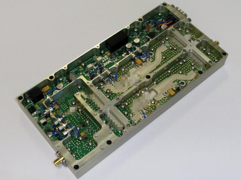
In the fully designed amplifier the stage discussed above is doubled in parallel and combined with hybrid couplers to form a balanced configuration.
There are three more driver stages designed in the same fashion. The layout of the finalized RF/microwave circuits is imported into Altium Designer and Figures 5 and 6 show the full mechanical and PCB design using Altium and SolidWorks.


During the testing of the early prototypes, some tuning and adjustments are typically made to the RF and DC/control circuitry, but after the design is finalised, usually very little tuning is done during regular production.
Large parts of the tests during prototype qualifications and tests in production are automated. This helps to shorten the development time and improves productivity. The automated tests are done using standard measurement equipment used with specially built test fixtures and software.
Figure 7 and 8 show comparisons of the measured and simulated small signal gain and the gain at full compression. The results are in very good agreement. The measured output saturated power is above 48 dBm across the 0.5- to 2.5-GHz frequency band and is again in very good agreement with the simulation.

Click image to enlarge.

Click image to enlarge.
Conclusions
Nowadays, you have to design fast and get it “Right First Time” to have any hope of commercial success. The trend is to make amplifiers that are smaller, with higher operational bandwidth, higher power and efficiency, and higher linearity to provide better value for money. An amplifier of the complexity discussed above typically needs to be ready for delivery to the customer in as few as 10 to 12 weeks after the order has been placed, even though the amplifier is often developed from scratch. To provide that kind of service requires specialised knowledge and experience and also specialised engineering development and production tools.
References
- Anthony J. Bichler, “An Introduction to Broadband Impedance Transformation for RF Power Amplifiers”, High Frequency design, January 2009.
- Cripps, S.C., “A Theory for the Prediction of GaAs Load-Pull Power Contours”, IEEE-MTT-S Int’l. Microwave Symposium Digest, 1983, pp 221-223.
- Cripps, S.C., RF Power Amplifies for Wireless Communications, Artech House, 1999, ISBN 0-89006-989-I.
- Abrie, Pieter L.D., Design of RF and Microwave Amplifiers and Oscillators, Artech House, 2009, ISBN 978-1-59693-098-8.
- Ivan Boshnakov, Jon Divall. “Tandem RF software programs streamline the design of power amplifiers”, website feature on Planet Analog and Microwave Engineering Europe, December 2002, https://www.eetimes.com/electronics-news/4164425/Tandem-RF-software-programs-streamline-the-design-of-power-amplifiers.
- Ivan Boshnakov. “First time right design of Class A power amplifiers using the novel power parameters”, Microwave Engineering Europe, February 2005.
- MultiMatch Amplifier Design Wizard, Pretoria: Ampsa (Pty) Ltd.; https://www.ampsa.com.
- Microwave Office is a registered trademark of Applied Wave Research, Inc.
 If you enjoyed this article, you will like the following ones: don't miss them by subscribing to :