Power Tip 73: Synchronizing makes for well-behaved power supplies
Power systems have become complicated over the years due to the requirement for multiple power supply rails. To meet these requirements, multiple switching supplies are often employed. One key decision to be made is whether to synchronize switching frequencies or to let each power supply switch independently. Not synchronizing results in less circuitry, while synchronizing may help to reduce filtering costs and lower electromagnetic interference (EMI).
To illustrate the impact of asynchronous operation, the circuit of Figure 1 was simulated with P-SPICE. The current sources represent the input currents to the supplies. Figure 1 shows the waveforms of the two power supply currents and the ripple voltage on the capacitor.
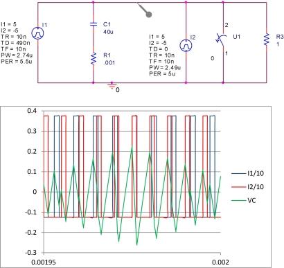
Figure 1: Beating effect on two asynchronous power supplies increases input ripple voltage.
Ripple voltage is at a minimum when the two converters are out of phase, and it is at maximum when they are in phase. In this case, there is almost a 2-to-1 difference in output ripple voltage. This is one of the strong arguments for synchronizing power supplies. You can reduce input voltage ripple by judiciously selecting the phasing of the various supplies. The second benefit is that the ripple current also can be reduced. In this case, when the supplies are out of phase with a 0.25 duty factor (DF) on each phase, the effective DF is 0.5, so the ripple current is:

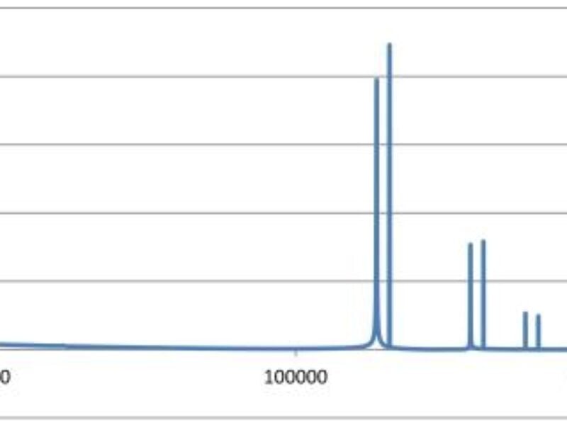
Figure 2: This FFT of input voltage simulation showsno sum and difference components.
The current sources were operating at 180 kHz and 200 kHz, and there are only fundamentals and harmonics of those switching frequencies. To generate sum and difference products, a multiplication is required, which is usually done with a nonlinear device like a switching diode or transistor (remember sin(u)sin(v)=1/2(cos(u-v)-cos(u+v))?).
However, if you examine the average voltage from which the power supply draws power during each cycle in Figure 1, you will find that it has a variation related to the difference frequency. It is then this frequency that can make its way to the output of the power supply through poor audio rejection in the power supply. This can be caused by ineffective voltage feedforward, hysteretic control, or ineffective current-mode control, and it is usually a second-order effect.
Another way this beating phenomenon can make it to the output of a power system is through a poorly designed grounding system. Ground current flow can create voltages much like Figure 2 in adjacent switchers. As an example, we had a power system that exhibited this. To prove the point, we conducted an experiment. We increased the bulk input capacitor and found we had no impact. Then we added small inductors in the power feeds to the switchers. We found that we minimized the interaction by keeping another power supply’s ripple current out of the ground of the victim supply.
Figure 3 shows an example of this phenomenon. If you look at the ripple voltage in purple and the switch node waveform in green, you will see that the ripple voltage has discontinuities when the switch node is in the low state. This is indicative of a second switcher’s current somehow adding to the first, not a modulation of the input voltage.

Figure 3: The power supply switching causes difference components.
A final reason to synchronize power supplies is that you can control the phasing of the power switches and, hence, their switching with respect to the remaining power supplies. If power supplies are not synchronized, multiple power switches may switch simultaneously. Each transition generates considerable noise, which may disrupt other decisions, causing chaotic operation.
To summarize, synchronizing your power system offers a number of benefits. It can reduce the ripple current in input filter capacitors. This allows you to save costs by using lower ripple current ratings or reduce the ripple voltage on the input of the power supply. It eliminates the possibility for the difference of the frequency components showing up in the output or input ripple of the power system.
It can make the power supply less prone to chaotic operation by controlling when the decision to change states in the power supply is made. Numerous multiple output power designs with and without synchronization are available in PowerLab. While you are there, examine some of the 1,400 reference designs that we have built, tested, and documented for your use.
Check out TI PowerLab Notes for a designer’s perspective on his power supply designs.
For more information about this and other power solutions, visit: www.ti.com/power-ca.
 If you enjoyed this article, you will like the following ones: don't miss them by subscribing to :