Power Tip 70: Use weighted feedback in multiple-output supplies to meet regulation specs
A good example is the low-power offline flyback shown in Figure 1, where both a 3.3- and a 5-volt output are required.

Figure 1: Resistor R18 provides the ability to weight output voltage regulation.
Regulation requirements for this design are ±5% for the 3.3 volts and ±10% for the 5 volts. A few techniques to improve the cross-regulation between outputs are included in this design. The transformer uses a single-tapped secondary winding to provide the 3.3 and 5.0 volts. This helps in two ways.
The cross regulation between the two outputs is influenced by the leakage inductance between them. Using a tapped-winding helps minimize the leakage inductance. If the 3.3 volts is the regulated output, the resistive drop in its winding is regulated out and only the voltage on the remainder of the 5-volt winding varies. Essentially, you get a variation on a 1.7-volt winding instead of a 5-volt winding.
R6 and D5 help the regulation when the 5-volt winding is lightly loaded and the 3.3-volt winding is heavily loaded. During this case, when the primary FET turns off, there is a lot of energy in the leakage inductance that can be peak-detected in a lightly loaded secondary. R6 and D5 provide a switched-load that draws little current until the voltage approaches the maximum regulation point.
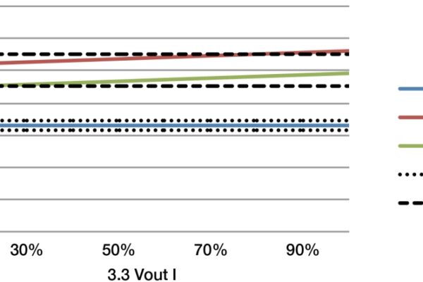
Figure 2 shows the cross regulation of the output voltages as a function of load current with R18 of Figure 1 open. The regulation of the 3.3 volt output is precise over all load combinations. The load line is flat with output current and the accuracy is set mainly by: the resistor tolerances, the reference tolerance, and its temperature characteristics.

Figure 2: 3.3-volt regulation only can force 5 volts out of the specification.
However, in this particular case, the 5.0-volt output is not well regulated and exceeds the specification. There are a number of factors leading to this poor performance. The first is the open-loop performance of the 5-volt output by itself. There are resistances outside of the regulated control loop on the 3.3-volt, output as well as the leakage inductance between the secondary windings that degrade the 5-volt regulation. These are the reasons that there are two 5-volt output regulation curves for a given 3.3-volt current.
In addition, loading the 3.3-volt output forces the 5-volt output higher. One example of such an effect is the 3.3-volt diode. At higher output currents, its drop is higher and the control loop forces the transformer voltage higher to compensate. This increased voltage proportionally raises the 5-volt output, which is why the 5-volt output curves slope up.
So far in this example, we have a 3.3 volt well within specification and a 5 volt out of specification. One thing we could try to do to improve the regulation is to close the voltage regulation around the 5 volts. In this case, the curves would reverse and we would find a well regulated 5 volts and a 3.3 volts with ±10% tolerance, which is clearly out of specification. We need to design for somewhere between these two extremes and take advantage of both regulation windows. You do this by populating R12 and R18.
To determine the total output variation needed to be accommodated, it is first necessary to generate a curve like that in Figure 2 and calculate the tolerance. By holding the 3.3-volt output constant, there is a ±12% variation in the 5 volts.
If you want to allocate the variation between the two outputs, you might allow 2% variation on 3.3 volts, and 9% on the 5 volts – giving 1% margin on each. To calculate the divider resistors, you first write a set of equations at the voltage extremes to calculate the current in R15 and solve for the ratios of the resistors. You find that the ratio is simply the ratio of the allowable voltage variation:

Subtracting the two equations and solving for the resistor ratios yields:

Once you have the ratios, you can pick one of the three resistors and solve for the remainder. For instance, if you set R18’s value, R12 is calculated from the ratio above. Then calculate the current through the two upper resistors. R15 is finally calculated knowing there is 1.25 volts across it and the sum of the two currents flow through it. Figure 3 shows how the regulation can be made specification-compliant at the expense of some performance of the 3.3V output.

Figure 3: Degrading 3.3-volt regulation brings the 5 volt into spec.
To summarize, you may not need to use multiple control loops to meet regulation requirements of multiple output power supplies. There are things that you can do to the supplies like preloads and tightly coupled windings to improve overall regulation.
Additionally, you can regulate multiple outputs with a weighted method, which allows you to control relative regulation between the outputs. An extra resistor in the feedback may save you a significant amount of circuitry. Please join us for the next Power Tip where we will look at the waveforms in a non-isolated DC/DC converter.
Check out TI Power Lab Notes for a designer’s prospective on his power supply designs.
For more information about this and other power solutions, visit: www.ti.com/power-ca
 If you enjoyed this article, you will like the following ones: don't miss them by subscribing to :