MOSFET-based current balancing cuts power use in supercapacitor stacks
As the use of two or more supercapacitor cells becomes prevalent in the design of a variety of battery operated systems, designers are looking for ways to optimize the circuitry around the cells configured in a series. Designs with greater power efficiency are high in demand because one of the goals is to extend battery life by reducing energy consumption.
One essential fact of using two or more supercapacitor cells in a series is that each cell has to be referenced against the others in order to achieve balanced voltages and prevent over-voltage of any one of the cells. Over-voltage causes stress and eventual failure of the supercapacitors.
There are two widely used methods of active cell balancing: One method uses an operational amplifier circuit to balance voltage in each cell, by essentially forcing a mid-point voltage between the supercapacitor cells. The other method uses a MOSFET array to balance the leakage currents in each cell by exponentially varying currents relative to selected operating voltages. This method compensates for leakage current imbalances with small voltage imbalances so that the maximum rated voltage limits are not exceeded.
For applications that depend on the lowest power dissipation to preserve battery life, the current balancing method provides superior energy efficiency for the supercapacitors, batteries and systems. Additionally, far fewer circuit components are required, board space is reduced, and the end result is lower cost and greater reliability.
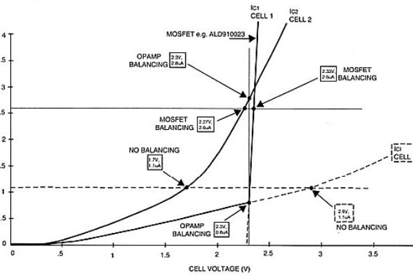
Below, a graph demonstrates how power dissipation of a supercapacitor series-connected stack differs in each method. Figure 1 charts cell leakage current (µA) versus cell voltage. It offers a comparison of individual cell leakage current both with op-amp-based voltage balancing and MOSFET-based current balancing.

Figure 1: The graph shows the difference between op-amp-based voltage balancing versus MOSFET-based current balancing for two supercapacitor cells used in a series. Note that IC1 and Cell1 is a near vertical line that shows the ALD910023 SAB MOSFET used for the current balancing, which forces Cell 1 to increase its total leakage current exponentially with incremental voltages.
The contrast between the two different methods of supercapacitor cell balancing is best illustrated with an example. In this example, the first assumption is that the total charge voltage (power supply) across two cells shown in Figure 1 is 4.6V.
The second assumption is that the cell capacitances of the supercapacitors are equal, thus C1 = C2.
Thirdly, the cells are balanced when cell leakage currents are equal, where IC1 = IC2.
Fourth, the individual Cell 1 and Cell 2 leakage current each follows its own specific current-versus-cell- voltage relationship. This is the result of the individual characteristics of each supercapacitor cell, which cannot be controlled and which can vary over a wide range of values and shapes. This is true even for supercapacitors made with the same material by the same manufacturer.
Most supercapacitor manufacturers only specify a maximum leakage current value, with some effort to “match” but not “guarantee” leakage currents, by housing two or more supercapacitors within a single package.
Without any external intervention or external cell balancing, natural cell balancing occurs where both cells have leakage currents at 1.1 µA, where Cell 2 settles to 1.7V and Cell 1 settles to 2.9V (see dotted lines). Cell 1, having exceeded its rated voltage of 2.7V, deteriorates rapidly and becomes damaged prematurely.
When op amp-based voltage balancing is applied, Cell1 (C1) is forced to a mid-point voltage of 2.3V at 0.8µA. Cell 2 (C2) is also forced to 2.3V at 2.8 µA leakage current plus 1µA for op amp current, which equals 3.8 µA for total power dissipation. The vertical line on the left in the graph above shows op- amp voltage balancing.
The solid horizontal line in Figure 1 demonstrates MOSFET-based current balancing. Using the ALD910023 device, Cell 2 balances at 2.27V at 2.6µA and Cell 1 balances at 2.33V at 2.6µA.
When MOSFET-based current balancing is used, with careful selection of SAB MOSFET part numbers and their corresponding charge voltages, the leakage current of one of the two MOSFETs is at zero, with zero power dissipation. Each supercapacitor cell balances at a leakage current level that is less than the maximum leakage of either one of the two cells. The actual balance current is less than whichever is higher of the two supercapacitor leakage itself, because the circuit is forcing that voltage a little bit lower.
The dotted horizontal line shows the supercapacitors with no balancing, but this is just a reference point because unbalanced supercapacitors cannot actually exist for long in a series without balancing. It will cause cell damage and eventual failure. The phenomenon of two or more supercapacitors linked in series is that whichever cell exhibits the greatest leakage subsequently forces its companion to exceed its rated voltage limit, which damages the materials in that cell. Once that cell is damaged, resulting in, for example, a short circuit, then the full voltage of 4.6V applies across the original leakier cell, causing damage to this cell as well, in a domino effect.
The MOSFET current balancing technique is very different from op-amp balancing, which uses balanced voltage balancing. An op-amp circuit will try to force the two cells to the same voltage mid-point of 2.3 volt and it burns power in doing so. If the two cells’ capacitances are not balanced, even ever so slightly, then there is additional current burn, or energy wasted, directly out of one of the supercapacitor cells. Depending upon the actual imbalance in supercapacitor capacitance, from their respective ‘natural’ voltages, this additional current burn may be substantially more than any of the leakage currents.
In an op-amp balancing scheme, Cell 1 is going to be set at 2.3V and 0.8 µA leakage current and Cell 2 is going to be forced to 2.3V at 2.8 µA leakage current. Assuming the op-amp also burns an extra 1µA, then total power dissipation will be 3.8µA.
With MOSFET current balancing, leakage current is reduced to 2.6µA for both cells, which is less leakage current produced by the individual supercapacitor at 2.8µA.
By balancing the current, MOSFETs also automatically balance the voltage of each cell (C1 – 2.27V, C2 – 2.33V) to be near voltage balance so that neither of them can damage the other with voltage that exceeds the supercapacitor limits of 2.7V. As the leakage (drain-gate) current of each MOSFET varies exponentially with its cell voltage, the apparent voltage imbalance between the two cells is actually a benefit, as each cell settles to a voltage that it is “comfortable” with and is more “natural”, without dissipating any excessive leakage currents or discharge currents. Nevertheless, it can be challenging to series-connect a whole string of supercapacitors to a much higher voltage than the 4.6V. Carefully matched supercapacitor cells and matched MOSFETs lend themselves more readily to series-connected high voltage, high power applications such as 50V or 100V systems.
All of the results demonstrated in Figure 1 have been successfully re-produced during third-party developer testing. Op-amp circuits are non-trivial, both in terms of component count and power draw. Even if a micro power op-amp is used, the circuit could draw much more power than the 3.8µA demonstrated in Fig. 1 if the supercapacitor cells aren’t nearly balanced in both capacitance values and leakage currents. Op-amp circuits can be less forgiving of supercapacitor capacitance mismatches between the cells.
Op-amps have some unknown variables associated with them because they force a mid-point voltage of each cell. Any time the supercapacitor stack wants to deviate from that voltage, a supercapacitor can burn a huge amount of energy, driven by the op-amp circuit. Supercapacitors are essentially low voltage, high current devices. If you try to force them to a different voltage, it takes a tremendous amount of current.
Power consumption is non-trivial for many battery operated systems, such as back-up power supplies or remotely located monitoring equipment where supercapacitors are used. These systems typically have to operate off the grid for long periods of time on battery charges. Reliability for water-level monitoring devices used on rivers or weather stations have to wake up occasionally, turn on sensors, record data and send it wirelessly to a collection point. Every milliwatt is important for these types of equipment to operate reliably between service calls and battery charges.
As supercapacitors used in a series of two or more becomes more prevalent in systems described above, engineers need to optimize efficiency, board space and cost. MOSFET-based current balancing for supercapacitor cells is more energy efficient than op-amp based voltage balancing MOSFETs are also a little more forgiving to mismatched supercapacitor cells.
 If you enjoyed this article, you will like the following ones: don't miss them by subscribing to :