The microscopic model of discharging in the case of a lead-acid battery
Introduction
Modeling of the operations of the batteries with electrical circuits has been developed in multiple dimensions from a simple capacitor to very complicated electronic circuits. These models take into consideration the state of the charge, the nominal voltage, capacity, aging, temperature, the discharging current, self discharge and other external and internal factors.
The purpose of this article is to understand the phenomena occurring at the electrode area by building a simulation model and its simple electronic circuit during the discharge of the battery. The voltage is the result of the accumulation of the electrons at the negative pole and the absence of the electrons at the positive pole. In an equilibrium state, when the external circuit is open, the charge and discharge reactions occur equally in both directions in the area of the electrodes.
When the external circuit is closed, the electrons from the negative pole will migrate to the positive pole through the external circuit, because the electrical field will act upon them. In the area of the negative electrode, where the reactions take place, the equilibrium is disrupted by the changes of the electron concentrations that occur. The system tends to equilibrium by increasing the quantity of the discharging reactions and decreasing the quantity of the charging reactions in both electrode areas. Initially the difference between the count of the discharging and charging reactions is at its maximum. During the time when the primary elements decrease and the secondary elements increase in the electrolyte, the battery is discharging. Henceforth we study and model the electrochemical phenomena in the unit of the electrode area.
Processes inside a unit of electrode area in the reaction zone
We consider a unit of an electrode area in the reaction zone from the negative electrode to have the dimension of one molecule, and this area can release multiple electrons at the same time in a single reaction. For simplicity we consider the battery fully charged with 10 units of primary elements that have access to this area. These 10 primary elements will release a few electrons through an electrochemical reaction. We also consider that the other elements do not have access to this area and do not have any influence on these processes, only these 10 primary elements and the secondary elements by which the reactions have been caused. At the initial equilibrium state of the fully charged battery we consider the lack of any electrochemical reactions in this area.
When the discharge begins, the primary elements in the electrode area react with each other and as the result of these reactions secondary elements appear and electrons are released. After that, these secondary elements change places with their primary element neighbors. This process lasts a over a finite time and is caused by the electrical field. The aim of the system is to recover the equilibrium state, because the released electrons migrate to the exterior circuit. The secondary elements resulting by the first reaction, cannot release other electrons to the electrode, they just occupy a place in this space. These secondary elements change their places with the nearest primary elements. The next step is the new reaction generated by the new primary elements in the electrode area, and then change places. This process continues until all primary elements are consumed and only secondary elements exist in the unit of this area. The end of the process corresponds to a fully discharged battery in this zone and these elements do not release other electrons to the electrode. In the charging mode the reverse reaction is produced by the secondary elements.
The timing of changing places in an ideal informatics model
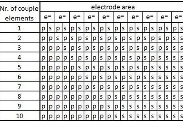
For simplicity we consider that the time of a reaction is equal to the time of changing places of two elements. We neglect the external influence of other elements on the 10. We consider that the elements are located along a line perpendicular to the electrode area. Other spatial distribution cannot be considered correct, because the neighboring places of this area are occupied by other elements outside our zone. We consider the electrical field homogeneous in the whole space that is studied. In Figure 1 we see a table of distribution of the primary and secondary elements and the evolution in time of all processes.

Figure 1: The primary (p) and the secondary (s) element distribution
In the first step the first primary element releases electrons to the electrode and as the result of the reaction a secondary element appears. In the next step the secondary element changes places with its primary element neighbor. The new primary element near the electrode area releases new electrons and after the reaction it transforms to a secondary element. Pending this time the secondary element produced in the first step changes places with its primary element neighbor. If the time of a reaction and the time of changing places of two elements are equal, then the result can be represented graphically as a line shown in Figure 2.

Figure 2: The time of a reaction and the time of changing places
The line has a rectangular form. The high level represents the release of the electrons, and the low level represents the pause, in other words the change of places of the elements.
The model of the electrical circuit
In the previous chapters we have concentrated on the microscopic phenomenon of the units in the reaction area and we have avoided detailing the command module and the relays which we consider ideal. We present the electrical schema of the circuits in Figure 3.

Figure 3: The battery model
The capacitors are fully charged with the unit of quantity of electricity (depends on the number of electrons released in one reaction). The C1-C10 capacitors are coupled to the external circuit only for the short time, when they release electrons. Every capacitor separately is commanded by the command module. In the first step C1 is connected and the first electrons are released to the external circuit. The time of this period is equal to the reaction time, when the first primary elements are transformed into the first secondary elements. The next step is the pause, when the first secondary elements change places with the next primary elements. In the next step C2 is connected and these steps continue until the last primary elements release electrons and transform into the last secondary elements. The graph, which represents this process, is shown in Figure 4.

Figure 4: Timing of connecting the capacitors in the external circuits
We consider that the time of connecting the capacitors is equal with the time of changing places of two neighbor elements.
Conclusion
This ideal microscopic model using an electric circuit helps us understand easier the phenomenon that happens on the unit area of the electrode in the reaction zone. In the case of a real model we must consider that the time of the reactions and the replacement of the primary elements with the secondary elements may be different, other elements situated outside of this zone in the electrolyte may have influence on the process, the time of the reaction in the case of different elements may be different, the spatial distribution of the elements may not perpendicular, the electrical field may not be homogenous and other internal and external conditions may have influence on the process.
 If you enjoyed this article, you will like the following ones: don't miss them by subscribing to :