Characterizing the dynamic output capacitance of a MOSFET
According to precedence, MOSFET datasheets show output capacitance at a single measured voltage. While these values were good enough for relative comparison between products in the past, it is misleading to use these values for modern devices. A better representation of product capacitance is needed.
The output capacitance of a MOSFET is voltage dependent; therefore a single point measurement does not accurately represent the capacitance characteristic of the device. Curve fitting can be used to find an output capacitance equation from this single point. Equation 1 below is an example based on capacitance at 25 V.

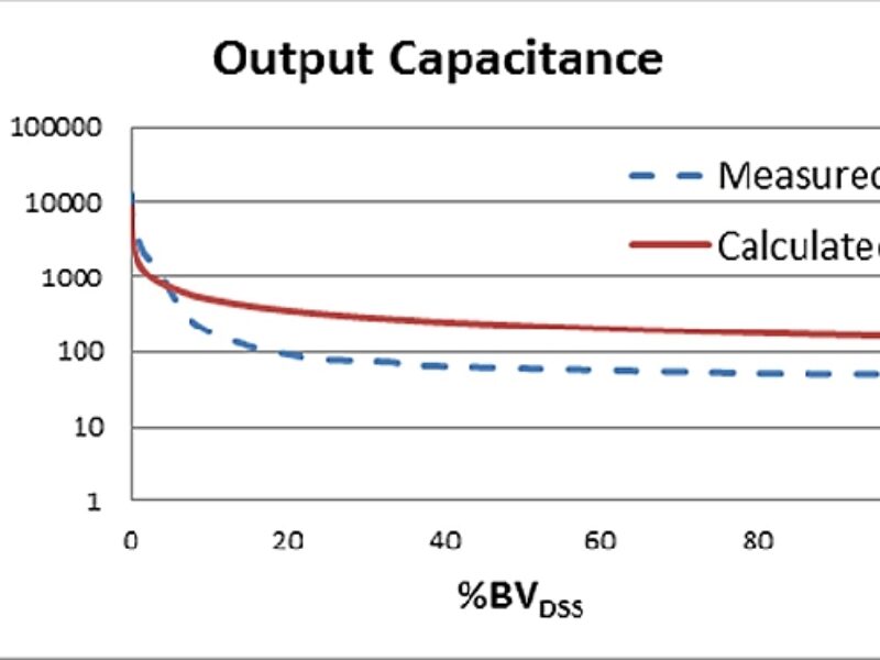
This formula’s integral could then be used in place of a single value capacitance in applicable equations. As shown in figure 1 and figure 2, equation 1 worked fairly well for planar devices however, more complex structures, like super-junction, are poorly represented leading to excessive error in any calculations.
Rather than creating a different equation to better fit the capacitance characteristic of each new device architecture, effective capacitance measurements can be used. Effective capacitance values represent the capacitance that results in the same charge time or charge energy up to a given voltage. These values take the change of capacitance into account without the need for complex formulas or integration like would be required when using equation 1.

Figure 1. Planar Output Capacitance Calculated per Equation 1

Figure 2. Super-Junction Output Capacitance Calculated per Equation 1
Using Effective Capacitance
Effective capacitance can be used in modeling energy loss and designing resonant topologies. When modeling energy loss for hard switching topologies, the energy stored in the output capacitance is lost as heat every switching cycle. As the switching frequency increases the switching losses approach conduction losses, dramatically affecting efficiency. The relationship of output capacitance to power loss is shown in Equation 2 [2], [3]. This is only one component of switching loss, but it is critical to consider. The additional power dissipation from switching needs to be taken into account when selecting a MOSFET and designing any heatsinking for the MOSFET.

In resonant topologies the effective capacitance is used to ensure zero voltage switching (ZVS). To achieve ZVS, the magnetizing current and dead time must be great enough to discharge the output capacitance of one MOSFET and charge another. If the magnetizing energy is too small, the circuit will operate in hard switching mode, losing some of the efficiency gained by changing to a resonant topology. If the magnetizing energy is too large, excess energy will be lost, again minimizing the efficiency gained through the use of a resonant topology. In order to design the circuit such that the magnetizing energy is as low as possible while still maintaining ZVS, the effective capacitance of the MOSFET must be used, as in equation 3 below.

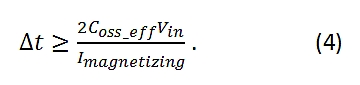
The effective capacitance is also needed to calculate dead time, ∆t,
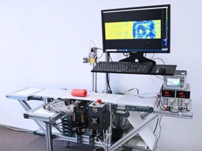
Measuring Effective Capacitance
There are several different ways to measure the effective output capacitance of a MOSFET. A constant voltage can be used to charge the output capacitance, giving a time related effective value. A second method is to charge the output capacitance with a constant current. Third, the capacitance versus voltage curve can be integrated, producing both energy and time related effective output capacitances.
The first method to measure the time related effective capacitance is a totem pole driver, depicted in figure 3. This driver will charge the MOSFET to its rated drain voltage through a 100 kΩ resistor while an oscilloscope monitors the drain voltage. The rise time (tr) of the drain to 80% of the rated BVDSS is measured. This, along with the resistor value, can be used to calculate the effective capacitance using equation 5 [3].

Solving for Coss_eff(tr),
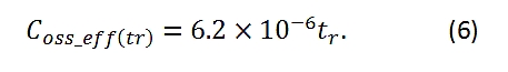

Figure 3. Effective Capacitance Tester Utilizing a Totem Pole Configuration
To measure the energy related effective output capacitance the MOSFET must be charged by a constant current per the circuit in figure 4. When the relay turns on the test starts. The time required to charge the output capacitance of the MOSFET should be measured and then applied to:
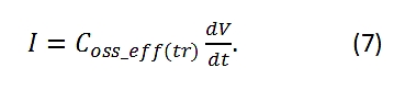
Where dV is 80% BVDss, I is the current used to charge the MOSFET, and dt is the time measured with the tester. When solving for Coss_eff(tr),
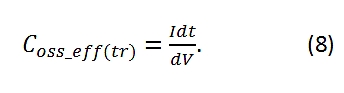
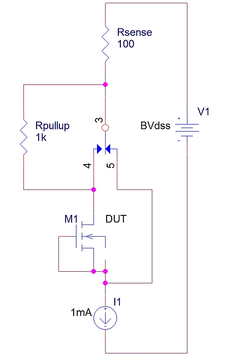
Figure 4. Effective Output Capacitance Current Based Tester
The other method that can be used to measure both time related and energy related capacitance is through the capacitance vs. voltage curve typically given in the MOSFET datasheet. This method is advantageous because it requires only a stock LCR meter instead of developing specialized equipment. A voltage-dependent capacitance function needs to be created to match the capacitance curve measured.
Once the function of capacitance vs. voltage is known, the time related effective capacitance can be found with equation 10, where C (V) is the voltage dependent capacitance function.

To get the energy related effective capacitance, use the same voltage dependent capacitance function in equation 11 [4].
![]()
Accuracy
Using the single point output capacitance measurement on datasheets can be a highly inaccurate way to estimate output capacitance. The voltage at which this point is taken varies from datasheet to datasheet and cannot accurately represent the entirety of the capacitance curve. By using the energy and time related effective output capacitance values, calculations will be more accurate. While even the effective capacitance values are estimations, they are sufficiently accurate for most calculations. The actual and estimated QOSS and EOSS values are similar at the point of 80% BVDSS. QOSS values can be used to calculate power loss by equation 12, where Poc represents the power loss due to charge stored on the output capacitance. This equation is simple for the user to understand and apply. It also happens to take the same form as the most common way of calculating drive power loss in MOSFETs. Of course, the conduction loss during switching still needs to be factored in to find the total switching power loss.

Conclusion
As operating frequency increases and resonant topologies become more prevalent, the output capacitance of the MOSFET starts playing a larger role in circuit performance. With its non-linear relationship to voltage, calculations can be cumbersome and time consuming. Effective capacitance is an easily obtained value that can greatly simplify calculations while still maintaining acceptable accuracy.
References
[1] Young, Sungmo. "Considerations on Output Capacitance for Soft Switching Converters." eeNews Europe (2011).
[2] Schultz, Charles. "Power MOSFETs: Reliable MHz Operation Requires Attention to Device Characteristics." PCIM magazine (1999).
[3] International Rectifier. "A More Realistic Characterization of Power MOSFET Output Capacitance Coss."
[4]Drofenik, U., A. Müsing and J. W. Kolar. "Voltage-Dependent Capacitors in Power Electronic Multi-Domain Simulations."
 If you enjoyed this article, you will like the following ones: don't miss them by subscribing to :