The benefits of the coupled inductor technology
Introduction
Coupled inductors are often used in multiphase topologies to take advantage of the current-ripple cancellation from magnetic coupling between the phases. Normally, current-ripple cancellation happens only at the output of the multiphase buck converter when typical discrete inductors are used. When these inductors are magnetically coupled, the current-ripple cancellation is applied to all elements of the circuit: MOSFETs, inductor windings, PCB traces.[1-6] Thus, the switching from all the phases affects each single phase, so the current ripple is reduced in amplitude and multiplied in frequency. Reduction in the RMS of the waveforms can improve the efficiency of the power converter or be traded for smaller magnetics, faster transient and, therefore, smaller output capacitance.
Coupled Inductors vs. Traditional Inductor Designs
The peak-to-peak current ripple in a traditional uncoupled buck converter can be expressed as Equation 1, where VIN is input voltage, VO is output voltage, L is the inductance value, D is a duty cycle (D = VO/VIN for a buck converter), and Fs is a switching frequency.
![]()
The current ripple in a buck converter with coupled inductors changes to Equation 2, for D < 1/N phases, where ρ = Lm/Lk is a coupling coefficient (Lm is magnetizing or mutual inductance; Lk is a leakage inductance), and N phases is a number of coupled phases.[6] This particular equation is limited to D < 1/N phases, which is often enough in a lot of applications, such as VIN = 12V to core (0.5V to 2.5V). Equation 2 allows you to easily see how circuit and magnetics parameters affect current-ripple cancellation.
![]()
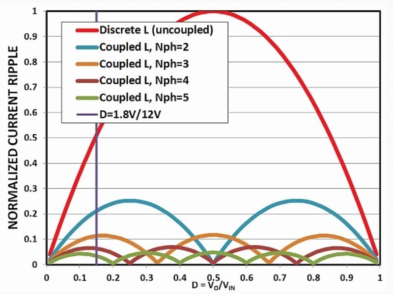
The additional multiplier in Equation 2, as compared to Equation 1, depends on application conditions. It changes due to duty cycle, coupling, and the number of coupled phases. Figure 1 shows normalized current ripple in discrete and coupled 210nH inductors in a 4-phase buck converter. The current ripple is normalized by a maximum current ripple: ripple in discrete inductor at D = 0.5 (so the normalized current ripple in a discrete inductor is 1 at D = 0.5). A typical application of 12V to 1.8V relates to the D = 0.15, as marked on the plot.

Figure 1. Normalized current ripple for a 4-phase buck converter: discrete 210nH and coupled 210nH inductors with different coupling coefficient Lm/L.

Figure 2. Normalized current ripple for a 4-phase buck converter: discrete 210nH and coupled 50nH inductors with different coupling coefficient Lm/L.
Figure 1 illustrates the dramatic current-ripple cancellation in all the power circuitry due to the coupled inductors. Notice that there are duty-cycle values where the benefit is significantly larger than around D = 0.15. Several plots for the coupled inductor illustrate the impact of the coupling coefficient Lm/L: for the practical coupling in Lm/L = 3 – 7 range, and some idealized and not realistic values Lm/L as 10 and 100. Assuming that the initial design with discrete inductors was reasonable and had acceptable current ripple, it makes sense to decrease the inductance value for the coupled inductor to achieve approximately the same current ripple around the targeted area D = 0.15. A value of 50nH/phase provides a similar current ripple as a discrete 210nH in this condition, Figure 2.
For the same peak-to-peak current ripple, the same RMS of current waveforms can be expected. This leads to the similar conduction and switching losses around all circuit branches and, therefore, a similar efficiency. The big benefit, however, is that a 50nH inductor will have > 4x better transient performance than 210nH, This benefit usually enables you to eliminate the big, unreliable, expensive, and bulkly output capacitance completely. Only the high-performance ceramic capacitors, the ones that are already present, remain.
Notice that ceramic capacitors always must be present for applications with a fast transient. This is because only capacitors with low ESR and ESL can provide a necessary transient performance at the instant of the fast load step. Bulk capacitors are typically added to address the slow-current slew rate in discrete inductors and associated energy storage. In the case of much faster coupled inductors, the capacitance from ceramic capacitors alone is usually enough to address the related, much smaller energy storage.
The benefits of coupled inductors do not stop there. Coupled inductors are designed with negative coupling, so the mutual fluxes from all windings cancel each other when all phases share the current equally. The latter condition is typical in multiphase applications, especially with a current-mode control. Only the leakage flux stores the energy in coupled inductors, so the energy storage for the example shown in Figure 2 is associated with 50nH/phase instead of a 210nH/phase. This implies that a coupled inductor can be fundamentally smaller or/and have a higher current saturation rating, as compared to a discrete inductor.
Compare two choices of magnetics for a typical 4-phase solution in a 12V to 1V application to deliver power to some microprocessor: off-the-shelf, high-efficiency discrete inductors FP1308R3-R21-R, and a 50nH coupled inductor CL1108-4-50TR-R. The related datasheets are available online.[7-8] Assuming a minimum of 0.5mm distance between discrete inductors on the PCB, the discrete inductors occupy ~722mm2 on the motherboard; the coupled inductor, already providing much better performance, requires only ~396mm2. This is illustrated in Figure 3. At the same time, the discrete inductor has Is = 80A at room temperature, +25°C, (It is certainly worse at a higher temperature.) while the coupled inductor saturates above 110A/phase at +105°C. The area reduction of > 1.8x and the saturation improvement of > 1.5x are achieved simultaneously.
To better appreciate the coupled inductor size, notice that discrete inductors (ones that are much more physically narrow) can be considered for this 4-phase solution, However, such inductors would either decrease the saturation rating or need a value smaller than the targeted 210nH. The latter case would, in turn, increase current ripple and decrease efficiency.
The multiplier responsible for the decreased current ripple due to magnetic coupling in Equation 2 can be simplified, assuming an ideal coupling (i.e., very high Lm/Lk). Then Equation 2 reduces to Equation 3.[3] It is apparent that a benefit on the order of N phases can be expected from this coupling, but it can also be higher depending on the duty cycle. To be more exact, even greater advantage can be achieved in different applications where the duty cycle is further from the D = 0 or D = 1 regions.
![]()

Figure 3. Magnetics of comparable efficiency for 4-phase 12V to 1V solution: four discrete 210nH inductors and a single coupled 50nH part. Graphic courtesy of Eaton Electronics.
A generalized approach to take advantage of the coupled inductors will now be shown. Equation 2 for current-ripple cancellation in a coupled inductor can be generalized as Equation 4.
![]()
The figure of merit (FOM) in Equation 4 can be derived from reference [9] by using familiar and more convenient parameters, as in Equation 5.
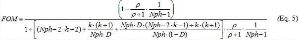
This FOM expression in Equation 5 is valid for a particular ![]() region of the duty-cycle D, where index k changes in the 0 < k < (Nph-1) range.
region of the duty-cycle D, where index k changes in the 0 < k < (Nph-1) range.
Figure 4 shows the current-ripple reduction for a different number of phases in a full range of the duty cycles. The current ripple is plotted assuming ideal coupling and the same value of L. Increasing the number of coupled phases is clearly beneficial.
Notice that purposely increasing the number of phases for a given output current is a cost- and size-ineffective approach for a typical solution with discrete components. This approach should also be very attractive with some commercial integrated solutions where multiple switching phases are integrated on a single die.

Figure 4. Normalized current ripple for a multiphase phase buck converter for ideal coupling and a different number of phases.
Figure 4 also marks a particular duty cycle D = 0.15, which corresponds to a practical example of VO = 1.8V for VIN = 12V. This condition is used for the curves in Figure 5, which shows how the choice of coupling coefficient ρ = Lm/Lk affects the current-ripple cancellation. Looking at Figure 4, the normalized current ripple in a discrete inductor is ~0.5 at D = 0.15, which is also shown as a rad curve in Figure 5. The 4-phase coupled inductor in the same conditions would have the same current ripple if coupling is very low; it would have significantly less current ripple as coupling increases.
See Figure 5. Notice that the current ripple decreases very fast initially, and then reaches a flat region at the large values of the coupling coefficient. This behavior recommends a coupling coefficient that is roughly in the 3 to 5 range. With this approach, the benefit of the greatest current-ripple cancellation is implemented, but the corner of diminishing return is avoided (i.e., no oversized magnetics for little or no benefit).

Figure 5. Normalized current ripple for a multiphase phase buck converter for D = 0.15 (VO = 1.8V, VIN = 12V application) as a function of coupling coefficient r = Lm/Lk.
Summary Guidelines
Assume that we start with a reasonable multiphase buck-converter design that has discrete inductors. The goal is to improve the system performance with coupled inductors. The initial design with discrete inductors is assumed to have a reasonable current ripple, so the efficiency of the converter meets customer expectations. For a 4-phase buck converter with a practical value of coupling coefficient, the plot of expected FOM in Equation 5 is shown in Figure 6.
Looking at Figure 6, and targeting D ~ 0.15, a FOM of 4 can be considered as a design target. Figure 7 illustrates the resulting current ripple: the red curve shows the initial ripple of discrete inductor L; then two curves show a current ripple for the L with different coupling; and finally, two curves are for L/4. As expected, current ripple around D ~ 0.15 is similar between discrete inductor L and the coupled inductor L/FOM = L/4.

Figure 6. A FOM for a 4-phase buck converter with coupled inductors as a function of duty cycle.

Figure 7. Normalized current ripple for a 4-phase buck converter: discrete L, coupled L, and coupled L/4.
Notice that, depending on the application, the targeted duty-cycle range can differ, and the chosen FOM can be higher than illustrated in the D ~0.15 example. The chosen FOM = 4 corresponds to a typical enterprise application, where the high-efficiency discrete 210nH inductors are replaced with 50nH coupled inductors, as in Figure 3. As expected, a much smaller inductance value has to satisfy the saturation requirement of the application, so the coupled inductor size is significantly smaller than in the conventional solution. The chosen FOM = 4 also translates to 4x faster current slew rate during the transient and, therefore, roughly 4x smaller output capacitance is expected.
The shown guidelines can be applied to any number of coupled phases. Notice that the chosen FOM does not have to be applied solely towards the transient performance. Depending on application conditions and customer priorities, some of the FOM can be traded, for example, directly to reduce current ripple which, therefore, lowers the conduction losses everywhere in the circuit. For example, the chosen FOM = 4 can be traded for only a 2.6x reduction of inductance value (and related transient improvement), leaving 1.5x for both the reduced current ripple and improved efficiency.
As coupled inductors are moving into different power applications, many different customers will now definitely benefit from this proprietary technology.
References
[1] Pit-Leong Wong, Peng Xu, P. Yang, and F.C. Lee, “Performance improvements of interleaving VRMs with coupling inductors,” IEEE Trans. on Power Electronics, vol. 16, no. 4, pp. 499–507, 2001.
[2] A. M. Schultz and C. R. Sullivan, “Voltage converter with coupled inductive windings, and associated methods,” U.S. Patent 6,362,986, March 26, 2002.
[3] Jieli Li, Charles R. Sullivan, Aaron Schultz, “Coupled inductor design optimization for fast-response low-voltage DC-DC converters,” in Proceedings of IEEE Applied Power Electronics Conference and Exposition, APEC 2002, pp. 817–823 vol.2.
[4] Peng Xu, Jia Wei, Kaiwei Yao, Yu Meng, F.C. Lee, “Investigation of candidate topologies for 12 V VRM,” in Proceedings of IEEE Applied Power Electronics Conference and Exposition, APEC 2002, pp. 686-692 vol.2.
[5] A.V. Ledenev, G.G. Gurov, and R.M. Porter, “Multiple power converter system using combining transformers,” U.S. Patent 6,545,450, April 8, 2003.
[6] Jieli Li, Anthony Stratakos, Charles R. Sullivan, Aaron Schultz, “Using coupled inductors to enhance transient performance of multi-phase buck converters,” in Proceedings of IEEE Applied Power Electronics Conference and Exposition, APEC 2004, pp. 1289–1293 vol.2.
[7] Datasheet for FP1308R3-R21-R (210nH discrete inductor),
[8] Datasheet for CLB1108-4-50TR-R (4-phase 50nH coupled inductor),
[9] Y. Dong, “Investigation of Multiphase Coupled-Inductor Buck Converters in Point-of-Load Applications”, PhD Thesis, Virginia Tech, 2009,
[10] T. Schmid, A. Ikriannikov, “Magnetically Coupled Buck Converters,” in Proceedings of IEEE Energy Conversion Congress and Exposition, ECCE 2013, pp. 4948-4954.
 If you enjoyed this article, you will like the following ones: don't miss them by subscribing to :