Add battery back-up power option to existing grid-tied PV and solar systems
Overview: Homeowners and businesses have bought into the concept of distributed power by installing solar energy systems. There are a lot of factors that have caused a significant rise in solar energy production. These include federal tax incentives, renewable energy incentives, cheaper photovoltaic (PV) solar modules, immediate and projected rises in energy costs, and increasingly stronger desires for energy independence.
Almost all residential, community and light commercial PV/solar systems fall into three types, the first being the most common:
- grid-tied capable of reducing dependency on utilities and saving money,
- off-grid capable of supplying electricity where a grid is non-existent, and
- grid-interactive where the presence of a connected energy storage system (usually in the form of a battery bank) enables the user to achieve both grid-tied benefits with off-grid independence.
The last type is especially useful in scenarios where the grid is down for a variety of reasons, when grid power is inadequate or problematic, or when grid power is costly making it advantageous to “offset” the grid using renewably-generated stored energy. Concerns about grid stability and even availability are more valid than ever, even in the developed world, as life-changing events such as historic storms, tsunamis, and other disasters are combining with increasingly routine brownouts, blackouts and other interruptions to raise anxiety levels about electricity supply to meet growing demand worldwide.
In areas where a lot of renewable energy is added to the grid, the effect of all this extra “peak demand” electricity can actually destabilize the “load demand” grid which relies on more conventional and less flexible or “dynamic” sources—once the sun stops shining or wind stops blowing PV arrays and turbines are effectively turned off, and that loss of peak electricity places even greater demands back on the relatively in-elastic grid which can’t always meet the need.

For these and other reasons, the benefits of storing up renewably-generated electricity for use when it is more advantageous are obvious. Energy storage can offset electricity use during peak times, provide off-grid independence during outages and emergencies, and contribute to greater grid stability to ensure that renewably-generated electricity can remain a vital and proactive partner in the energy mix. This is why energy storage-based systems represent the fastest growth area in solar installation today, and why industry surveys show battery-charging capable inverters to eclipse grid-tied “string” inverters in the next two years (Photon International 2012).
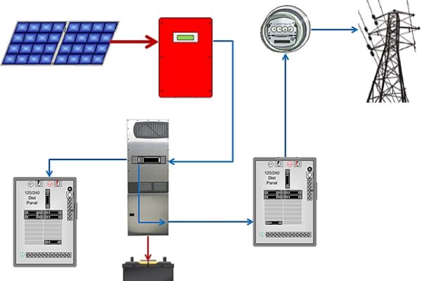
The basics: As mentioned previously, by far the most common configuration of a PV generation system is an array of PV modules feeding a grid-tied (GT) inverter that converts the DC power to AC power, then fed through the building’s service panel and on out to the electrical grid (see Figure 1). The grid acts like a battery and the renewable energy is placed on the grid for collective consumption, which, in turn, reduces generation other sources. The grid-as-a-battery is a great concept, until it’s no longer there – the grid-tied inverter requires the grid to stay powered per the UL1741 requirement for safety reasons. Without grid power to keep the GT inverter operating, the available PV power just sits on the roof unused. And during an outage, a home or business with PV electricity potentially available is in the dark just like everyone else.
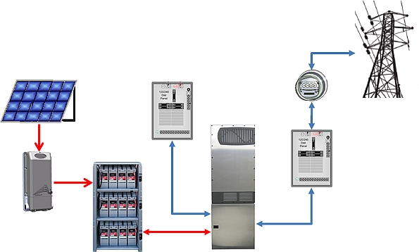
A battery-based (BB) inverter system does not require the electrical grid to stay active, and is the mainstay of off-grid homes, businesses, and industrial installations such as cell phone broadcast towers. Using battery-based off-grid technology, a smarter type of “grid/hybrid” inverter technology is able to use PV, wind, hydro-electric and other renewable DC energy sources to keep the batteries charged and sell the excess to the grid, just like the grid-tied unit using the grid as its battery (see Figure 2).
For those that have not yet invested into a solar energy system and would like to have backup power, a grid/ hybrid inverter/charger with battery back-up is the best choice. Solar energy can still be sold back to the grid, while having the security of knowing your PV based renewable energy system will still provide power during an outage until the electrical grid is back up and running.
Why not purchase a grid/hybrid inverter from the start? For those staring at their roof full of PV modules when the grid goes down, fully inoperable while the hours without power turn into days, and sometimes even weeks, that very same question is probably being asked many times over. Some may not have realized they would be without the PV power on their roofs when they bought their grid-tied system. Maybe they thought it would never happen to them. Finally, the relatively modest extra cost of a smarter grid-interactive inverter/charger and batteries may have initially discouraged them.
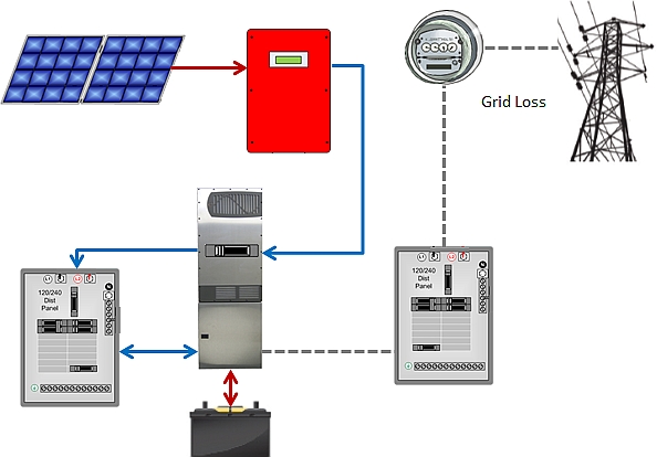
Adding energy storage through AC-coupling: For the owners of these more common grid-tied, grid-dependent inverters, there is a way to tie in a battery-backup inverter system using a method called AC Coupling. It typically requires adding a load center with circuit breakers and electrical connections for the building’s critical loads. This allows a point at which the grid-tied (GT) inverter and the battery-based (BB) inverter to “couple” and share their energy to the loads. In a normal mode of operation with grid power available, the energy from the PV array flows through the GT inverter to the critical load panel, with any excess energy flowing through the load panel to the BB inverter, and on out to the grid (see Figure 3).

When grid power is lost, the BB inverter activates an internal transfer switch which opens its connection to the grid. This keeps the inverter from trying to power other homes on the grid, as well as keeping energy off the power lines so utility workers don’t get shocked. The BB inverter also provides a power source to the GT inverter that keeps it online and “inverting” the DC power to AC power for the critical loads (see Figure 4).
When the sun goes down and the PV power is no longer flowing through the GT inverter to the loads, the power stored in the batteries will now provide power to the critical loads panel until morning (see Figure 5).

When the sun comes out the next day, the system reverts to the power flow as shown in Figure 3, with any extra energy used for recharging the batteries. If no excess is available then some manual load-shedding (divesting of less critical loads to prioritize the most critical, such as lighting and refrigeration) may be necessary through the turning-off of the critical load panel connected devices until the batteries are charged. If the critical loads are absolutely essential and load shedding is not an option, then adding a generator to the backup system can satisfy the critical load demand while charging the batteries.
One might ask: “why not just add the generator and forget about the BB based inverter? “That might be a viable option for some, but there are some important things to consider before making that decision.
1. The generator will need to run the entire time that electrical energy is demanded by the building’s loads, perhaps 12-18 hours per day. Aside from the noise factor, many low-cost generator motors require frequent maintenance, and are very inefficient at low power output.
2. As an example, higher efficiency can mean the difference between filling up a 5-gallon gas tank once a day versus once a week if the generator is tied into a battery-based backup system that is running the generator just a couple of hours a day. News photos and videos of the aftermath of extreme weather and other emergency events show people standing in long gas lines for hours, and even then not always successfully. Many of the gas stations that had gas couldn’t pump their storage tanks without available grid power!
3. In a BB inverter system augmented with generator power, the batteries can greatly extend generator runtime—the same fuel will go a lot further since the generator does not need to run 24/7.
Typical AC-Coupling solutions: Like any solution, the devil is in the details, and AC Coupling a GT and a BB inverter together is no different, especially if one wants a “one size fits all” solution for all applications. That “one size fits all” package usually includes one or more diversion loads, possibly a blackout relay or some other method to take the GT inverter offline to prevent it from overcharging the batteries on the BB inverter. And it requires a lot more upfront design to be sure all devices in the system can handle all possible conditions.
Some battery-based inverter manufacturers attempt to simplify their AC Coupling implementations by “dithering” or altering the frequency of their power to the GT inverter outside its operational window of 59.5 to 60.5 hertz. This will effectively shut it off when the batteries are full instead of using a blackout relay, thereby saving the cost of the relay. However, in many instances frequency dithering prohibits the use of a generator as the generator frequency is not always stable enough for the GT inverter to synchronize to. Even if it synchronizes, there is a risk of back-feeding and damaging the generator in low or no load conditions.
It should also be noted that the “one size fits all” AC Coupling solution really needs diversion loads to divert any excess energy in systems that either have too much PV power and/or too small of a battery bank which could put dangerous charge levels into the batteries. While it can be argued this energy can be used to heat water or run pumps, that “benefit” often comes when not necessarily demanded, and if the diversion load can no longer accept the available energy, the GT inverter must still be shut down. In addition to the complexity, diversion load implementations can also be expensive, requiring undesirable invasive installations which can make this design a poor choice for those who want simplicity and cost control in their AC Coupling system. The extra expense of all the associated control and coupling hardware plus adding a more expensive inverter/charger often means skimping on energy-storage with lower-grade batteries and enclosures, lowering overall system performance and utility.
OutBack’s AC-Coupling solution: another approach is to keep things elegantly simple by outlining some basic sizing and operational guidelines by which a simple BB inverter, a battery bank, and a remote-operated relay can be added to an existing GT inverter system to tie in the building’s available PV power to the critical loads during grid loss. The rest of this article discusses an advanced electro-mechanical solution from OutBack Power with an option for automatic generator control if desired. Unlike most frequency dithering solutions, our control circuit consists of the two OutBack inverter Auxiliary (AUX) ports and two OutBack relays. This cleaner, more compact component design allows the safe lock-out of the GT inverter when the batteries are full, and also keeps the GT inverter locked out if an optional generator is started and running in the system. Integrated with a more advanced, smarter inverter/charger such as OutBack’s Radian series with dual AC inputs and advanced generator features, the result is a system that achieves higher performance at lower effective cost.
Notable features of the OutBack GSLC175-AC-120/240 AC-Coupling solution include:
- UL-1741 end-to-end—when used with an OutBack battery rack, the entire system is specifically for this application, ensuring fully-compliant operation.
- Split-Phase design—more easily integrated into standard household wiring without costly, inefficient transformers
- Dynamic Stability—more stable output provides a cleaner signal to the system’s grid-tied (GT) inverter during load spikes and variations, ensuring it remains on-line producing electricity.
- Universal design—works well with other brands and models of GT inverters.
Grid instability, extreme weather and earthquakes are all factors to consider, and geographic and seasonal vulnerabilities will affect the choice of which loads are most critical. Following are a few guidelines on how to size the system and interact with the two types of inverter systems.
Guideline Number One: The daily critical load watt-hours shouldn’t exceed 80% of the watt-hours available from the battery bank. An off-grid system is typically designed to discharge the batteries no more than 50% per day to extend the life of the batteries. However, this assumes that the backup system will only be used a few days or perhaps a week or two per year, so discharging batteries to an 80% depth will not significantly reduce their life below what is considered the normal life cycle for a battery. Cycle-testing of OutBack’s Energy Cell batteries has shown that 600 cycles are possible for 80% depth of discharge (DOD) on sealed AGM batteries, which translates to 600 days of backup power if sized to provide a day’s worth of power.
The rate or speed of which the batteries are both charged and discharged will affect their overall capacity. The slower the rate of charge or discharge, the more capacity in the battery. The following table shows the typical capacity for one to six strings of batteries. One would take 80% of these numbers to estimate how much power is available to the loads for a 24-hour period. This is reflected on the 12-hour discharge rate in the next sizing table.
Table 1 – Power for various rates of discharge on the OutBack Energy Cell 200RE AGM battery.

Under normal operating conditions when the grid is present, an OutBack BB inverter/charger will keep the batteries in a “float” charge which is a small charging rate that replaces the energy lost inside the battery due to self-discharge. However, when the grid is lost, the inverter is no longer in control of the charging current going into the battery. The BB inverter is in the “invert” mode providing AC power to the GT inverter so it can stay online and provide energy to the critical loads. Any remaining power not needed by the loads will flow back through the bidirectional H-bridge circuit of the BB inverter into the batteries in an unregulated charge.
In most cases the power generated by the PV array that is passed through the GT inverter goes to both the loads and the unregulated charge onto the batteries, and, if the system is sized properly, the unregulated charge onto the battery bank will not exceed the maximum charge rate. However, in a worst-case scenario where the critical loads are all or mostly off, the current from the GT inverter should not exceed the maximum charge rate onto the battery bank. OutBack’s remote-operated circuit breaker (ROCB) design can easily take the GT inverter offline when the batteries are detected as being full.
The following table shows the maximum PV power per string of battery so the maximum charge rate is not exceeded, as well as the associated available power for a given 24 hour period. This system sizing should keep the system in balance depending on the combination of solar radiation available to the array and how much power is needed based on load demand. Since the relationship between available PV power and load demand is highly unpredictable, on sunny days the battery bank may get charged quickly and even turn off the GT inverter while the sun is still shining; it does so to prevent the batteries from being overcharged. On cloudy days, the battery bank may not get fully charged from the PV array and a generator may need to finish the charge on the batteries. If a generator is not part of the system, the premises occupants will face some hard decisions about which loads to keep up-and-running and which ones to divest or “shed” until more sunny days arrive.
The PV power column is the maximum amount of power that can be back-fed through the inverter to charge the batteries. The calculation for this guideline presumes some losses on the array and in the GT inverter.
Table 2 – Matching PV power and load demand with the OutBack Energy Cell 200RE AGM battery at the 12 hour discharge rate and 80% depth of discharge.

The load kWh demand should be matched to equal one of the values in the table above to the actual PV array size and the loads that will be moved to the critical load panel. Typical load profiles can be used as illustrated in Table 3 for some typical critical loads for assistance in making this estimate. Note that the refrigerator cycles for typically 15 minutes out of every hour.
Table 3 – typical critical load profile.

So now when matching the 12.4 kWh of daily usage to the battery capacity table, we can see that one string of batteries will not be enough. While two strings will be sufficient, the array size would have to be 4 kW or less. If the array is 6 kW then three strings would be required, as the battery bank must be sized large enough to handle the maximum unregulated charge rate in a worst-case scenario. The alternative would be to go with the “diversion load solution.” However, by the time the cost, complexity and invasiveness of the diversion loads and diversion load protection and control are added together, eliminating a string of batteries does not really actualize any savings.
Guideline Number Two: The OutBack inverter power rating should be 1.25% of the GT inverter power rating. This guideline ensures that the GT inverter does not overwhelm the charging circuitry in the OutBack inverter if the load demand goes to zero and all available GT inverter power is flowing to the OutBack inverter. While admittedly an unlikely scenario, for safety and equipment protection it’s best to follow this guideline. For example, the 8 kW rating of the Radian inverter would dictate a GT inverter no bigger than 6 kW.
Guideline Number Three: This ensures that either the daily load demand or battery charging don’t exceed the power from the PV array, or adds an optional generator to the backup system. A previous section of this application note described a scenario when available PV power exceeds load demand, requiring that the GT inverter is disconnected with an OutBack remote operated circuit breaker if the excess power begins to overcharge the batteries. In reality, the condition in a backup system whereby the available PV power is out-producing the load and battery charging demand is unlikely. Critical loads will rarely turn off completely and many conditions, especially on cloudy days, will require supplemental power to meet load and battery charging demand.
Most of North America has 3-5 average sun hours per day which translates to 18 kWh to 30 kWh of available PV power with a 6 kW array, notwithstanding various losses that could reduce the daily production significantly. However, sometimes PV production will meet or exceed the PV module nameplate so for estimating purpose 18 kWh to 30 kWh are the working numbers to use in determining what to expect in sunny weather.
Assuming all loads in the previous example are on at once, they will be drawing an average of 1.4 kW per hour of available power from the PV array through the GT inverter. That leaves 4.6 kW for battery charging if the PV array is achieving its nameplate power production. If the three-string battery bank starts the day at 80% depth of discharge (DOD), then it would take about 4.2 hours (19.5 kWh ÷ 4.6 kW = 4.2 hrs) to charge the battery while simultaneously providing the 1.4 kW demanded by the loads. At the point of GT inverter shutdown when the batteries are full, load demand can be sustained for nearly 14 hours before reaching 80% DOD on the battery bank—likely enough to last from sundown until bedtime with enough power left in the batteries to provide a power source to the GT inverter the next morning so it can deliver power from the PV array and start the cycle over again.
However, on cloudy days or when daily sun hours are below average due to winter conditions, adding a generator can assure adequate backup power under all conditions. A 5 kW generator would take 5.4 hours to charge the battery bank for another 14 hours of operation while also maintaining the 1.4 kW load demand (19.5 kWh ÷ (5kW1.4kW=3.6kW) = 5.4 hrs). As stated before, a generator running at 85 to 90 percent of maximum output can increase hourly operational fuel use significantly, compared to running the generator at low load conditions. Avoiding noise, lack of fuel availability and high maintenance cycles are additional benefits to higher fuel efficiency when using a generator with a battery-backed up inverter system.
A more detailed look of OutBack’s GSLC175-AC-120/240 AC Coupling solution (including some drawings) follows; here is a list of the required AC Coupling components that come with and OutBack pre-wired AC-Coupling Radian Load Center.
- 50A DPST Remote Controlled Circuit-Breaker (ROCB; takes three CB spaces in the load center)
- OBR-16-DIN (12 VDC Outback Relay)
- OBR-XX-DIN (48 VDC OutBack Relay)
- DIN Rail Hardware
The ROCB comes pre-wired as do the two OutBack relays and two AUX Ports. The L1 and L2 conductors from the GT inverter or its AC disconnect are landed on the open ends of the dual-pole circuit breakers ganged to the ROCB. If a generator is installed, then the two-wire start lines are connected to the 48V GT lockout/Gen-start relay, with the L1 and L2 from the generator going to the Gen Input bus bars, and the ground and neutral lines going to the correct bus bars. All other grid input, inverter output, and DC battery connections are landed like any other Radian load center application. The GT and generator connections are indicated by white X’s in the following photo.
Photo: GT and Generator Connections

Advantages to using the ROCB over a solid state relay include the ability to manually disconnect the GT if for some reason there was a malfunction in the system. Manual disconnect also allows using the bypass so the GT can still sell to the grid if the BB inverter must be bypassed for any reason. This is not possible with a solid state relay and would require external hardware with a frequency shift solution, making the ROCB a much easier and more cost-effective AC Coupling implementation.
In addition to the ROCB and relay devices, a new AC Coupling function has been added to the MATE3 user interface. This function uses temperature-compensated charging set-points for the current active charging mode, will disconnect the GT using the ROCB when the battery voltage is 0.4 VDC above the battery voltage to protect the batteries, and will reconnect when the battery voltage is 0.4 VDC below the current temperature compensated charging set-point. If there is abundant surplus power from the GT, then ROCB cycling may be as frequent as six minutes. Manually turning on more loads connected to the critical load panel, or using a diversion load, can decrease the cycling, but it will not harm the ROCB as the cycle of the circuit breakers and ROCB motor exceed 10,000 cycles. If the system is properly sized and loads defined as “critical” typically remaining running, frequent cycling should not be a problem and will not damage any of the OutBack devices.
Other smart features of the AC Coupling MATE3 function include a regular 15 second check of the high battery set-point in the event the occupants manually close the ROCB when it should be open, and will re-open the ROCB to ensure the batteries are not overcharged through user error. Another feature is the MATE3’s checking for an active grid when the ROCB has an open command, so if the grid power returns while the ROCB is open then the MATE3 will re-close the ROCB and allow the GT to return to selling to the grid. The GSLC175-AC-120/240 AC Coupling load center comes with a Quick-Start Guide which includes detailed diagrams of the control circuit and MATE3 inverter settings.
Overall, this AC Coupling solution from OutBack has considerable advantages: it is easy to size, easy to install, does not require external hardware, and is less expensive. It uses intelligent temperature compensated controls and provides back-feed protection if a generator is part of the system. While simpler and more cost-effective than the frequency dithering-dependent “one-size-fits-all” approach of other AC Coupling schemes, the OutBack solution provides safer, more stable and generator-friendly battery backup power for existing grid-tied inverter systems up to 6 kW that won’t leave all that PV power stranded on the roof the next time disaster strikes. When implemented using the OutBack Radian-series inverter, the result is higher-performance and greater reliability in a more compact, cost-effective package, enabling the user to invest in higher-quality energy storage and thoroughly optimizing their renewable energy system.
Figure 6 below shows a simplified single line diagram of the AC Coupled system. The drawing shows the generator option which is not required if daily sun is expected or critical loads can be shed until more sun is available.
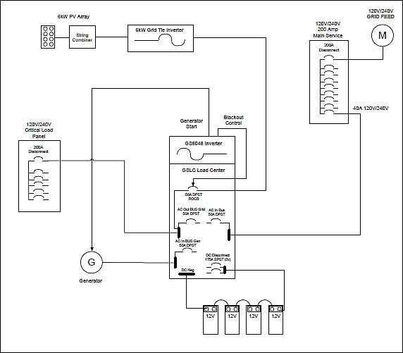
Figure 6 – Single line diagram of an OutBack Radian inverter AC Coupled to a Grid-Tied Inverter
Figure 7 below is a detailed wiring diagram of the Radian GSLC175-AC-120/240 GSLC load center. Field wiring lands on the terminal bus bars as designated below with “X”. If desired, a two-wire generator start can be connected to pins 21 and 24 of the 48V relay.

Figure7–Detail diagram of the Radian GSLC175-AC-120/240 GSLC load center wired for AC Coupling. Field connections designated with “X”.
About the author
 Mark Mays is an applications engineer at OutBack Power focusing on system design, configuration, field commissioning and troubleshooting of both off-grid and grid connected solar energy systems. Previous industry experience included power quality audits, product development of power quality analyzers, development and delivery of CEU training programs in power quality and electrical troubleshooting for the electrical utility industry, licensed electricians and electrical engineers.
 If you enjoyed this article, you will like the following ones: don't miss them by subscribing to :