Using film and aluminum electrolytic caps in power converters for voltage stabilization in HV grids
Storage elements that buffer energy of the most diverse forms, and make it available for subsequent conversion processes, are significant components in modern power supplies and frequency converters. A great deal of attention is paid to smoothing and the uniformity of the energy source, and a capacitor’s ability to store large electrical charges plays a special role in this.
In general, the larger a capacitor’s facing plates, the larger its capacity. However, the realization of high capacities in a small volume is crucial for the limited installation space in modern equipment. In addition, the special demands of electrical engineering place great significance on dielectric strength. Film and electrolyte capacitors are typical examples of devices suited to these applications.
Film capacitors, especially metalized film capacitors, are based on a winding of two layers of metalized polypropylene. The thickness of the polypropylene foil (insulator) determines the rated voltage, which can approach several kV. A special characteristic of polypropylene capacitors is their self-healing ability. Due to the very thin foils generally used, this ability is extremely important in avoiding short circuits after flash-overs. Further design-related properties include low ESR, ESL, and a relatively wide working temperature range.
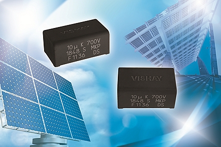
Figure 1: A film capacitor is almost an ideal device for solar applications in that its capacity does not change significantly with temperature, it remains almost unchanged during charging and discharging, and it can be used over an extended frequency range.
Aluminum electrolyte capacitors consist of two layers of aluminum foil separated by one or two layers of paper, and impregnated with a conducting fluid (the electrolyte). Their operating voltage is limited to approximately 500 V due to the thickness of the oxide layer of the first aluminum foil and the properties of the electrolyte. Important device properties include a very high charge storage capacity and small dimensions relative to the capacity.
However, since the electrolyte capacitor is polarized, it can only be used to a limited degree in an alternating current environment. And while the aluminum electrolyte capacitor has a higher capacitance per unit volume, the capacitance values vary with temperature and frequency due to its specific construction. Ohmic and frequency-dependent losses cause heating during charging / discharging, which limits possible ripple current. Furthermore, electrical properties change over time due to chemical processes, which can lead to an increased failure rate after the end of the specified service life.
Ceramic capacitors are resistant to extremely high voltages due to the ceramic materials used for their insulation. Very finely ground paraelectric / ferroelectric basic materials are sintered at high temperatures to a capacitive element, which as a dielectric serves as the electrode support. Ceramic capacitors can only store small magnitude charges, and are generally used for filter purposes at high-frequency voltages. In these applications, the phase and neutral conductors are short-circuited to ground via the capacitors. High-voltage capacitors, available in today’s market, can process over-voltages in the range of several kilovolts.
Modern power supplies and converters reach increasingly high power densities up to the megawatt range. Modern semiconductors enable switching of high loads at constantly increasing frequencies, making possible high-power converters in compact designs at acceptable costs. However, with increasing power densities, the requirements on capacitors rise.
Generally, a converter input circuit, which is structured more or less extensively, is distinguished by the energy source. Especially in the case of solar converters, the input value depends on the sunlight intensity and is therefore subject to large variations, making the arrangement of an optimal operating point difficult. Therefore, a DC energy storage device must be provided at the input. The input circuit capacitor is implemented with electrolyte capacitors due to the high-DC-voltage component, the required high storage capacity, and their ability to be correspondingly over-sized. The capacitor is barely stressed, since very high alternating components cannot be expected.
Requirements for an intermediate circuit capacitor, also known as a DC-link capacitor, are significantly more complex. They function as energy storage devices between the DC / DC converter and the DC / AC inverter, and their input currents contain very high alternating components (ripple). The output-side voltage must be smoothed well, so that a stable DC voltage supply to the inverter is ensured. Typical examples of low-capacity converters are metalized polypropylene capacitors from the MKP1848 series, while capacitors from the HDMKP series are suitable for larger converters.
If the available space is too small, or if more energy must be stored, aluminum capacitors offer a suitable alternative. For applications in the load range of 100 kW and more, an intermediate circuit capacitor — often with larger aluminum capacitors can be set up.

Figure 2: Inverter service life of more than 20 years can be achieved with good component dimensioning based on the expected load profile using devices such as Vishay’s 193 PUR-SI Solar or 159 PUL-SI.
When it comes to component cost, aluminum capacitors provide a clear benefit; a 470 μF / 450 V aluminum capacitor costs only one fifth that of a comparable film capacitor. However, foil capacitors require little protection circuitry to restrict the effects of failures. High switching frequencies and steep switching flanks require the use of damping capacitors (snubbers). The task of the snubber MKP386M is to reduce or eliminate voltage and current spikes and switching losses. Noise emissions (EMI) are reduced by the suppression of the voltage and current overshoot caused by the switching of semiconductors.
As an alternative, developers are increasingly employing complex switch algorithms in power electronics for pulse width modulation in order to increase efficiency and to improve network quality. Such designs employ higher frequencies and harmonics, which must be filtered at the output using LC and LCL filters. AC filter capacitors, such as the MKP1847 series, offer an extended capacitance range, various connection configurations, and, for increased safety, so-called segmented film technology corresponding to the UL810 standard.
Consideration of overload and fault behavior takes the spotlight with increasing power density. The damage can take the form of a short-circuit, an open circuit, or something in the middle (higher leakage current); and if overheating occurs, the electrolyte can leak due to pressure reduction and the drying out of the winding.
Stable High-Voltage in Spite of Changing Loads
The increasing integration of renewable energy sources, such as wind and solar energy, confronts the grid with new challenges. Capacitors for voltage stabilization in the high-voltage grid are in a completely different application field than usual capacitors, and have different design requirements and dimensions. They serve to maintain the standard requirement, according to which the mains voltage at the end user may not deviate by more than 230 VAC, ± 10 %.
The additional provision of capacitive reactive power can stabilize the voltage; the voltage can be raised or lowered by a slight shift of the phase into the capacitive or inductive area. To do this, shunt reactors or capacitor banks can be connected as required. Overhead lines act inductively at high loads. The voltage drops and increases again if the phase is shifted by capacitive reactive power.
In addition to voltage stability, voltage quality is also a significant consideration for the grid operator. Harmonics — superimposed voltages that always possess a multiple of the fundamental wave frequency — add to the fundamental wave during operation. Normally the third harmonic (150 Hz) is the most pronounced in heavily loaded grids, so it must be significantly reduced. The corresponding filter installations normally lie in the power range between 200 MVA and 300 MVA.
The reactive power reduction is provided by a mechanically switched capacitor bank with damping (MSCDN). If a large load is present in the grid and the voltage must be supported, this is provided by connecting capacitors to each phase. The reconciliation of capacitors C1 and C2 with the high-voltage reactor L induces the 50 Hz current component to flow through the C2 unhindered. However, frequencies close to the center frequency are passed through the resistor and converted to heat. The interference frequency is reduced significantly.
Design of the Individual Capacitors
Capacitors are formed by wound elements. The devices can be operated optimally at voltages up to approximately 2 kV, so numerous elements must be connected in series to achieve the required withstand voltage of 250 kV to 300 kV. To allow these huge capacities to be transported and installed in a modular manner, specialist manufacturers can now assemble the wound elements in stainless steel casings and weld them to provide a hermetical joint. Such devices are called medium-voltage capacitors.
The high voltage connected to the first capacitor (C1) is distributed over a series of 30 to 40 capacitors, resulting in a voltage of approximately 7.5 kV per capacitor. The weight of the capacitors is restricted to a maximum of100 kg, allowing less than 10 parallel capacitors to be connected per series. One C1 capacitor has a capacitance of 35 µF to 40 µF. These capacitors consist of several winding elements, which are connected internally to form serial winding groups. In the second capacitor (C2), the connected 30 kV to 40 kV are distributed over approximately five capacitor series. That results in 7 kV per capacitor with a capacitance of around 45 µF.
The technical implementation produces a very large plant. The electrodes of one capacitor winding element consist of an aluminum foil, in addition to the dielectric consisting of several layers of polypropylene foil. If all foils necessary for such a project were lined up next to each other, a band 8,000,000 m long would be created. That is much more than half of the world’s axis, and the area of the foil could cover 350 standard FIFA football fields.
Expressed as weight, more than 10 tons of aluminum and approximately 25 tons of polypropylene would be needed. To pack this large active surface in a compact form, the aluminum and polypropylene foils are first wound to a round form and then pressed flat. These flat windings are stacked, connected, insulated, and then assembled and hermetically sealed in rectangular casings. The total weight of just the capacitors, including the casings and connectors, adds up to much more than 50 tons.

Figure 3: To master the high voltage of 250 kV to 300 kV phase-to-ground in accordance with the regulations, frames are developed for the capacitors, upon which each horizontal assembly is installed using individual capacitors. These frames are separated electrically using insulators and assembled at the customer site to form a tower 7 m to 10 m high. A total of 30 to 45 frames are required depending on the power of the plant.
These numerous examples demonstrate the variety of capacitor applications in power electronics and electrical engineering. They can also be used as supplements in further applications, such as hybrid and electric vehicles, electricity meters, and control of high-power drive.
 If you enjoyed this article, you will like the following ones: don't miss them by subscribing to :