Multirate techniques fuel advances in digital power conversion
For decades, analog technology has formed the cornerstone of power converter topologies. Although most converters use switching techniques and pulsewidth modulation, the implementation circuitry has been predominantly analog for compatibility at a process level for power semiconductors as well as cost-effectiveness. But the situation is changing. The drive for greater efficiency in data centers and telecommunication systems is exposing the shortcomings of analog technology and its derivatives.
Digital power management and control provide real-time intelligence that enables system developers to build power systems that automatically adapt to their environment and provide optimized efficiency for each specific use-case. The use of intelligent digital power ICs allows automatic compensation for changes in load and system temperature and enables energy savings through the use of adaptive dead-time control, dynamic voltage scaling, frequency shifting, phase dropping and discontinuous switching modes.
One obstacle to the rapid adoption of digital power has been its perceived expense, but any differential between analogue and digital control is fast disappearing with the introduction of the latest components, such as Intersil’s ZL8800. Digital power efficiency and cost is now equalling or bettering comparable analogue power-conversion solutions, while providing more advanced features.
Most importantly, the pulse width modulation (PWM), loop control and feedback are implemented digitally. Analog signals are converted to digital using analog-to-digital converters (ADCs) and once the signals are digital, microcontrollers, digital-signal processors or computational state machines control the digital PWM and the feedback loop. This has important advantages in terms of maintaining stability without the compromises on responsiveness from which analogue control often suffers.
Although digital control offers advantages, many manufacturers are not taking full advantage of what the technology offers and have, in many cases, simply implemented in digital form the core analog PWM techniques. Digital control makes it possible to build far more flexible control loops and take advantage of multirate control in which individual algorithms are tuned to handle events that happen at different speeds.
Traditional digital PWM controllers are uniformly sampled. The controller samples the error in output voltage and from that computes the required duty cycle for the next switching cycle. The downside of uniformly sampled controller is the latency or group delay from sampling the error to when the PWM controller is able to switch the power-supply circuitry appropriately. The group delay translates to phase lag, which increases with frequency and places an upper bound on the achievable closed-loop bandwidth.
Multirate control makes it possible to provide stable power but react almost instantaneously to sudden changes in voltage, providing an appropriate response within a single PWM switching cycle. The only way to achieve with this conventional architectures is to employ variable-frequency switching techniques, using higher frequency sampling and control when the voltage is changing rapidly. But this is not a useful approach for many systems. Modern telecommunications equipment and other applications with stringent electromagnetic compatibility (EMC) demands require fixed-frequency operation so that they can maintain tight control of the noise spectrum.
Another approach is to apply a proportionate gain that is linear to the error voltage deviation. Using only a proportionate gain it is possible to achieve single cycle reaction using fixed-frequency switching but a fast-response loop gain can lead to instability.
The ChargeMode technology developed by Intersil and used in the ZL8800 dual-channel/dual-phase DC/DC controller uses a mixture of uniform and multi-rate sampling techniques, which samples the error and computes the modulation signal multiple times during a switching period. This technique significantly reduces group delay and therefore supports very high bandwidth operation. The phase lag is significantly reduced due to the reduction of group delay. The device also uses a dual-edge modulator, which outperforms competitive and so-called ‘leading-edge’ modulators in terms of total group delay.
Figure 1 shows ZL8800’s dual-sampling technique. The total delay (tdelay) is the sum of ADC conversion delay and computation delay (including pipeline/filter delays) using either of the sample rates. By using the higher-frequency NxFsw clock in Figure 1, the device clearly demonstrates a reduction of tdelay compared to a conventional, uniformly sampled PWM modulator.
Armed with an error signal from high-frequency sampling, the ChargeMode controller uses a novel strategy to overcome the instability of using just high loop gain. This is performed by localising the effect of a change to one or a few cycles. If the duty-cycle effect propagates to the next few cycles, then it may lead to the point of instability. Using digital control it is possible to ensure that what is done to the duty cycle to cope with a sudden voltage deviation in one switching cycle is undone within the next switching cycle or next few cycles. This technique is known as “a single-cycle response” (ASCR) digital compensation.

Figure 1 – ZL8800 Digital PWM Modulation
The compensator block diagram, shown in Figure 2, has many similarities to a traditional digital proportional-integral-derivative (PID) controller architecture used in conventional PWM control strategies. But it has significant differences. The diagram indicates how the multirate sampling technique is integrated within the compensator. The compensator has two parallel paths for processing the quantised error voltage. One is called the ‘fast path,’ which samples error voltage more frequently than the ‘slow path.’ Using this novel compensator structure, the duty-cycle command is fed back to determine the effect of the fast path and to nullify the fast path effect in the following cycles.
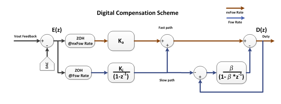
Figure 2 – ASCR Digital Compensator
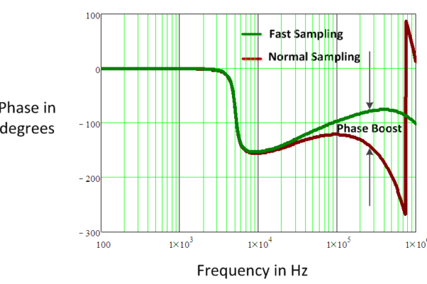
The compensator structure has reduced delays between the error sampling instant and the duty-cycle decision. This translates to a natural phase boost at high frequencies, which provides stability and makes it possible for high-bandwidth designs, as shown in Figure 3.
Through the use of multi-rate sampling and control, the ASCR compensator can achieve an inherently stable control loop, which only needs to be tuned for bandwidth specification. In a wide range of output filter configurations, only ASCR gain needs to be varied to reach the desired closed-loop bandwidth operation. To allow higher performance, there is a second parameter that can be user controlled: the residual. This is a dampening factor, essentially setting the response rate of the loop.

Figure 3 – Phase boost at high frequencies
A potential drawback of conventional multi-rate sampling technique is the injection of switching frequency harmonics into the feedback loop due to oversampling of the error. The ZL8800 overcomes this problem through the use of a low-latency ripple filter in the fast path – all repetitive elements of ripple are totally rejected. All that remains are the non-periodic elements in the waveform including transient steps with little or no delay, resulting in more than 20dB of ripple reduction without a significant time delay allowing high gains and higher bandwidths.
PWM control is only part of the overall solution. Having the digital controller in a highly integrated mixed-signal silicon technology process allows the integration of power management with power conversion.
The advanced power systems found in the latest generation of base-stations, routers and other data-communications infrastructure designs use digital signalling over the serial Power Management Bus (PMBus). The PMbus has become the standard protocol for communicating with power conversion systems using a digital communications bus. Using PMBus and PMBus-enabled devices for power conversion provides flexibility and control that is not possible with traditional analog power systems. Even adding a new power is simplified using the PMBus. The digital power IC for the new rail is provided with its own SMBus address and is added to the system and there is no need to reprogram or add more stand-alone power-management ICs because of the additional voltage rail. As it is supported by PMBus, the new rail is automatically integrated into the standard monitoring, sequencing, margining and fault detection schemes.
Digital control can go further. For example, Intersil’s single-wire Digital-DC (DDC) serial bus allows power ICs to communicate with each other, supporting complex distributed functions such as inter-IC phase-current balancing, sequencing and fault spreading, eliminating the requirement for complicated power supply managers that are often accompanied by numerous external discrete components.
The use of software also provides the ability to program device behavior even after PCB assembly, allowing easier prototyping as well as system tuning for semicustom subsystems. Although some advanced power systems may require extensive programming and coding experience from users to set up the commands and functionality required to access the capabilities of digital power management devices, the PowerNavigator software written by Intersil for the ChargeMode-technology devices enables the simple configuration and monitoring of multiple DDC devices via the USB interface. The tool makes it easy to change all features and functions of a digital power supply design using a simple graphical user interface. Through simple drag-and-drop graphics users can simplify and create an entire power management environment without having to write a single line of code.
As a result, through the combination of more advanced digital processing, communications and software control, digital power can provide higher efficiency power delivery with lower design cycle times.
 If you enjoyed this article, you will like the following ones: don't miss them by subscribing to :