How much power can you get from a brick?
When the high-power brick industry emerged some 20 years ago, 100-150 W was the practical limit. Now there are suppliers offering quarter-brick IBC (intermediate bus converters) at up to 864 W, e.g. Ericsson’s PKM-NH series, and power density figures that could not even be imagined a few years back. Customers are pushing power per board towards 1 kW and projections are as high as 3 kW to satisfy the most power hungry computer chips. Even if the power brick efficiency figures are increasing asymptotically towards 100%, this will put very high demands on thermal management in the power brick as well as in the end-user system.
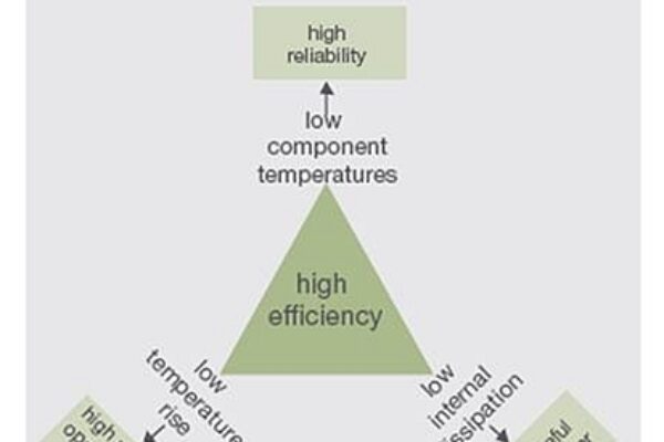
Power density is one of the most frequently promoted parameters of BMPS (board-mounted power supplies) and high-power bricks in particular. However, of much more practical importance than the power density rating is the maximum operating temperature and efficiency. Efficiency is exceedingly important for several reasons, it determines: the losses in the system and the amount of cooling required; how much utility power is “wasted” rather than being used for the desired purpose; the physical package sizes of both the BMPS and the final system; and the operating temperatures of the components and the resultant system reliability.

In actuality, all three of these criteria – efficiency, operating temperature, and reliability – are very interrelated and reinforce each other. Unlike the more typical situation in engineering where desired properties need to be traded-off against each other and cannot be simultaneously optimized, here there is a synergistic relationship between three very desirable properties that can all be obtained with a proper design. That is why BMPS manufacturers put so much design effort into maximizing the efficiency of their products.
Intermediate Bus Converters
The intermediate bus architecture is the common power solution for high-power computer board applications. A regulated or non-regulated Intermediate Bus Converter (IBC) provides isolation and the intermediate bus voltage powering the POL regulators that provides the final supply voltage for the computer chips.
Information and Communication Technology (ICT) equipment supplied by power systems with battery back-up during mains failure have a wide input voltage range of 40.5 – 72 V dc standardized by ETSI EN 300 132‑2, and normally use regulated (fully regulated or semi-regulated) IBCs. The regulation function is accomplished by changing the duty cycle of the converter, i.e. the percentage of time that the converter’s power switching devices are active. Conversion efficiency is very high but limited by the power losses in the free-wheeling diodes and output filter inductance and the higher voltage rated power MOSFETs required due to the relatively high maximum input voltage.
The voltages in EN 300 132-2 is defined at the interface between the power plant and the ICT equipment. The actual BMPS operational input voltage range is affected by resistive and dynamic voltage drops in the power distribution and is therefore specified to 36 – 72 V dc.
Datacoms equipment with a narrow input voltage range, e.g. 45 – 56 V dc, may use non-regulated IBCs. They operate as DC transformers with fixed 50% duty cycle and have transformer turns ratios of 4:1 or 5:1 when stepping down the voltage from the 48VDC system voltage level to an intermediate bus voltage of 12 V dc or lower. The fixed 50% duty cycle minimizes the power losses in the freewheeling diodes and output filter inductance and the conversion efficiency is typically a little bit higher than in regulated IBCs.
Safety Regulations
The core safety standard that applies to ICT equipment is IEC 60950‑1 Safety of information technology equipment. Now in its second edition, this standard underpins regional adoptions such as Europe’s EN 60950-1 and UL/CSA 60950-1, which applies in the US and Canada.
The standard describes appropriate measures to assure safety, such as the need for isolation barriers and protective earthing. The standard’s guiding principle is to provide two levels of protection from electric shock and energy hazards that may trigger other dangers, such as fire. This two-level model creates a hierarchy of protection measures that build upon five categories of insulation:
- Functional insulation
- Basic insulation
- Supplementary insulation
- Double insulation
- Reinforced insulation
Functional insulation is necessary for the product to function properly. It may reduce the likelihood of ignition and fire hazards, but provides no reliable safety protection from electric shock.
For ICT equipment, the output side of isolated BMPS, such as high-power bricks, normally shall meet the criteria for a SELV circuit that limits voltages to a safe level of maximum 60 V dc under both normal operation and single fault conditions. The isolation requirements that the brick must then satisfy depend on the level of isolation that the AC/DC front-end power supply provides, together with the system’s arrangements for connection to protective ground.
Generally, the AC/DC power supply in ICT equipment has reinforced or double insulation (alternatively basic and/or supplementary insulation) between the AC line supply and its DC output. Furthermore the output and the input of the BMPS connect to protective earth. This means that the system already include two levels of protection from electric shock and energy hazards. Consequently, functional insulation is adequate for the BMPS in almost all practical system implementations.
If the normal input voltage exceeds 60 V dc, it must additionally withstand an electrical strength test and pass fault condition testing. The isolation voltage in the electrical strength test depends on the input voltage and the working voltage in the IBC circuitry, and typically ranges from 1000 to 1400 V dc. Commercially available isolated BMPS almost invariably specify 1500 V dc isolation, which has become the industry de-facto standard.
Clearly, safety is a crucially important factor, which tempts some high-power brick manufacturers to exploit safety requirements in their marketing material—for instance, claiming that 2250 V dc is necessary to meet the isolation voltage requirements. In fact, only the IEEE 802.3af PoE standard for devices that distribute network power via Ethernet data cables requires this level, and only then for specific central-office PSUs that supply power to lines that traverse outside environments, such as links between buildings.
Clearly PoE is not an application where standard high-power bricks are used. If the user is not familiar with the terms and definitions in the safety standards, it is easy to confuse unqualified marketing claims with the 1000 to 1400 V dc isolation voltage that IEC 60950‑1 requires for standard BMPS.
Paralleling
Despite the very high power and current levels provided by today’s IBCs, there are current demands that are even higher than the output of a single brick. In such cases, the power system designer may consider the option of paralleling two or more units. Another circumstance in which paralleling is sometimes used is for the implementation of ‘n+1’ redundant designs, where one additional BMPS in addition to the number required to power the system is used to provide for uninterrupted system availability in the event of one BMPS failure.
Direct paralleling is the most straightforward approach to paralleling. Two units are directly connected and there are no other connections between them. The difficulty with this approach is poor load current sharing. Even though each unit have the same nominal output voltage, there will be some variation in the absolute setting. The unit with the highest output voltage setting will supply most of the current, and may even begin to go into current limiting before the other unit supplies appreciable current. In addition to this dependency on output voltage setting, the degree of current sharing is also affected by the following factors:
- The output regulation characteristic or ‘stiffness’ of the output voltage
- The output voltage vs. temperature characteristic
- The impedance of the distribution system between the units and the common load

The designer can control the degree of current sharing by changing the resistance in the board distribution traces. As RD is made larger, the voltage drop across it due to current from the higher voltage converter will bring the load voltage to the point where the lower voltage converter will supply current. The power dissipated in RD represents a loss of efficiency, so RD must be selected carefully to balance the need for current sharing with the need to minimize system power losses. Direct paralleling is the only alternative for non-regulated IBCs.
Active current sharing is the best performance approach, but does require external components and interconnections, and must be supported by the design of the BMPS being used. It is also possible to configure active current sharing by means of external circuitry for BMPS without internal provision for current sharing. Active current sharing requires regulated IBCs.
Thermal Management
Ever increasing efficiencies, advanced components and packaging are making power ratings higher and higher so that the power density, in terms of watts per cm3, now is an order of magnitude higher than that of older technology used some 15 years ago. The latest power bricks in the market are advertising an impressive 37 W/cm3 (600 W/in3), which put very high demands on efficient internal thermal management. Because electronics components such as semiconductor devices are sensitive to high temperature, it’s essential to make sure the components in high-power bricks are cooled properly and are operated at a reasonable temperature. Unless the heat transfer mechanism is extremely efficient, the power system design and reliability can be jeopardized.
The primary cooling mechanisms that could be used to cool electronic equipment are conduction and convection. Component power dissipation (Pd,comp) and component junction‑to‑case thermal resistance (Rth,J-C) for each critical component becomes extremely important as they determine the actual junction temperature that limits the BMPS thermal performance i.e. the maximum case temperature.
The temperature difference between the component junction and case can be calculated using the following equation
ΔTJ-C = Pd,comp x Rth,J-C
Forced convection offers greatly improved thermal performance and can also significantly reduce the required size of equipment enclosures.

Open-frame or planar BMPS have become popular as their thermal performance has improved and their superior cost structure offers compelling value. Some key issues to consider are: the thermally limiting component varies depending on operating conditions; orientation with respect to airflow is more critical; depending on the layout, any one of the four orientations could be the "best" or "worst" orientation for thermal performance; and as temperature differences among components become larger, all critical components will need to be monitored during thermal testing.
The technical specifications of high-power IBCs contain thermal derating curves to indicate how much current a BMPS may deliver without causing excessive thermal stress to its components for a given airflow and local ambient temperature.
Derating constraints are the maximum component temperatures used to determine the BMPS maximum output power or current under a certain operating condition. Semiconductor devices (power MOSFETs, ICs, etc.), are typically specified to TJ,max = +150°C. Most manufacturers, however, are using TJ,max = +125°C for their thermal evaluation purposes due to concerns about long-term reliability and to meet the derating requirements in IPC9592A Requirements for Power Conversion Devices for the Computer and Telecommunications Industries. FR4 PCB are limited by their UL ratings, typically +120°C or +130°C, and also the magnetic cores have stringent temperature limitations due to concerns about aging and "thermal run-away" at higher temperatures.
To use the derating chart the user needs to know the worst-case airflow and air temperature in the vicinity of the IBC. With this information, the maximum current that the IBC can deliver without critical component temperatures being exceeded can be read from the graphs.
Manufacturing Considerations
Another important aspect is the manufacturing considerations encountered by the end user. Typically IBCs are mounted by plated-through-hole attachment and require attention to detail if an efficient manufacturing process is desired. With increase of power density, IBC suppliers prefer to fabricate their PCB with heavy copper laminates for the purpose of reducing resistance and thermal conductive resistance. This is challenging for the soldering process because the large thermal mass of the IBC makes it difficult to get enough heating to the solder joint without risking damaging the PCB. It also creates huge problems if the IBC must be replaced.
A solution to this problem could be separate connectors soldered to the PCB where the IBC could be screw mounted. An example is the press-fit power connector that is designed to bring power to PCB applications. It allows for wire-to-board connections with common terminals. This version has press-fit pins and the IBC can be connected with screw mount terminals.
Of course this will require a new design of the connection terminals and may even require a completely different and standardized form factor.
Trade offs
The non-regulated IBC have typically somewhat better efficiency compared with the regulated types, but are not suitable in wide input range battery operated systems and are not suitable for paralleling. Due to the high risk of continuous over-current in parallel operation, non-regulated IBCs may even be over-heated resulting in drastically lower reliability and shorter lifetime increasing the system’s total cost-of-ownership. Regulated high-power IBC bricks and active paralleling adds complexity to the system, and typically entails accepting some performance and cost compromises, but may be the only practical alternative when power demands reach 1 kW and above.
System designers frequently interpret safety standards differently. In some circumstances, market pressures from suppliers and end-users may influence accepted practice and impose further restrictions. However, higher isolation voltage, e.g. 2250 V dc vs. 1500 V dc, typically have a negative effect on the efficiency of the BMPS and hence it is important to understand and clarify what is really necessary in terms of the safety and isolation requirements that high-density power bricks must meet.
High-efficiency and high-power-density regulated IBC bricks with wide input range and high isolation voltage are very challenging. Manufacturers are even forced to lower the isolation voltage to 750 V dc for example to improve efficiency. However, based on Ericsson’s research, new technologies such as hybrid-regulated ratio could expand high efficiency and high power density technology outside the datacoms segment to the general ICT domain matching the EN 300 132‑2 wide input voltage range.
Given sufficient forethought, it is possible to meet IEC/UL/EN 60950-1’s safety requirements alongside the important considerations for optimizing the high density power brick’s efficiency and reliability while lowering the systems total cost-of-ownership.
 If you enjoyed this article, you will like the following ones: don't miss them by subscribing to :