20-V, 2.5-A synchronous monolithic buck with current and temperature monitoring
Increases in digital IC integration, coupled with advances in printed circuit board layout and assembly techniques, continue to push system performance and power density higher.
Many of these systems, powered from a 12 V rail or battery stack, utilize point-of-load regulators to maximize power chain efficiency while maintaining a small form factor. The LTC3626 synchronous, monolithic step-down regulator is ideally suited for these operating environments, given its ability to provide a flexible, highly efficient DC/DC conversion while occupying a small footprint.
The device is capable of supplying 2.5 A of output current over an input voltage range of 3.6 V to 20 V from a 3 mm × 4 mm, 20-pin QFN package. Its patented controlled on-time architecture yields outstanding transient response and enables high step-down ratios at high switching frequencies, minimizing board footprint.
The LTC3626 integrates a number of easy-to-use, but powerful, features that would normally require additional ICs and design time to implement. Specifically, with the addition of just a couple of passive components, the device can be configured to provide accurate measures of its output current, input current, and on-die temperature. It can be just as easily programmed to limit each measured parameter.
These built-in features expand the designer’s insight into the performance of the system and increase the level of control with remarkably little extra design investment. Additionally, optional internal loop compensation is available to minimize the design effort.
The device also includes user-selectable Burst Mode operation or forced-continuous mode, resistor-programmable switching frequencies from 500 kHz to 3 MHz, power good status output, output tracking capability, and external clock synchronization.
Current monitor and limit
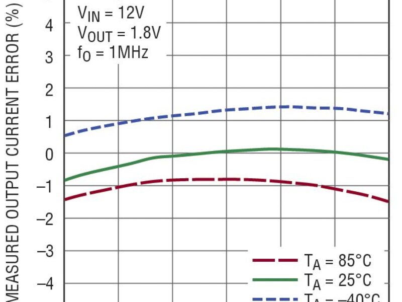
The device makes it easy to monitor the supply current by producing a fraction of its average output current at its IMONOUT pin; specifically, the current at the IMONOUT pin is equal to the average output current divided by 16,000.

Figure 1 shows the typical performance of the output current measurement for an ambient temperature range of -40°C to 85°C. Figure 2 shows the error between the actual average output current and the average output current as measured by the device.
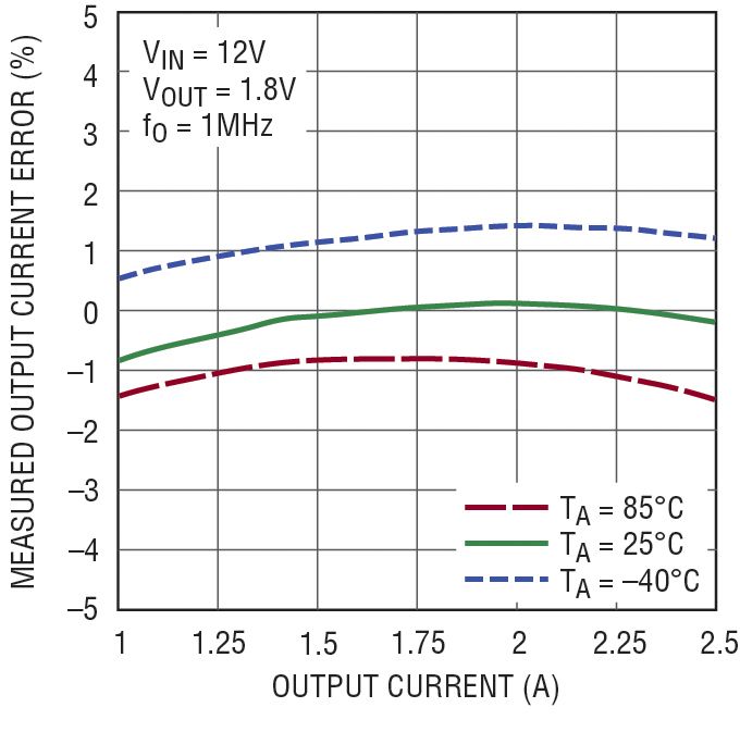
Figure 2. Output current monitor error vs output current
The current at the IMONOUT pin can be measured directly or converted to a voltage by placing a resistor from the IMONOUT pin to ground.
Converting the output of the IMONOUT pin to a voltage makes it easy to scale the output for digitization via a microcontroller or stand-alone ADC. Figure 3 shows the LTC3626 configured to run with the output current monitor activated while the LTC2460, 16-bit ADC, digitizes the result for digital processing.

Figure 3. 12 V input to 1.8 V output,
2.5 A regulator with digital output current monitoring
The LTC3626 also features an easily programmed average output current limit. Specifically, the device contains an on-chip current limit amplifier with a reference of approximately 1.2 V. To program an average output current, simply size the resistor from IMONOUT to ground such that the resultant voltage is 1.2 V for the current at which the limit should be activated.
Similar to the average output current, the device produces an estimate of the average input current at the IMONIN pin. That is, the current at the IMONIN pin is an estimate of the average input current divided by 16,000. Just like the average output current, the device offers a simple mechanism to program a limit for the average input current. This feature is useful for applications that must limit the average current drawn from the input supply. Figure 4 shows the LTC3626 configured to limit the average input current to 475 mA while producing an output voltage of 2.5 V from a 5 V input voltage.
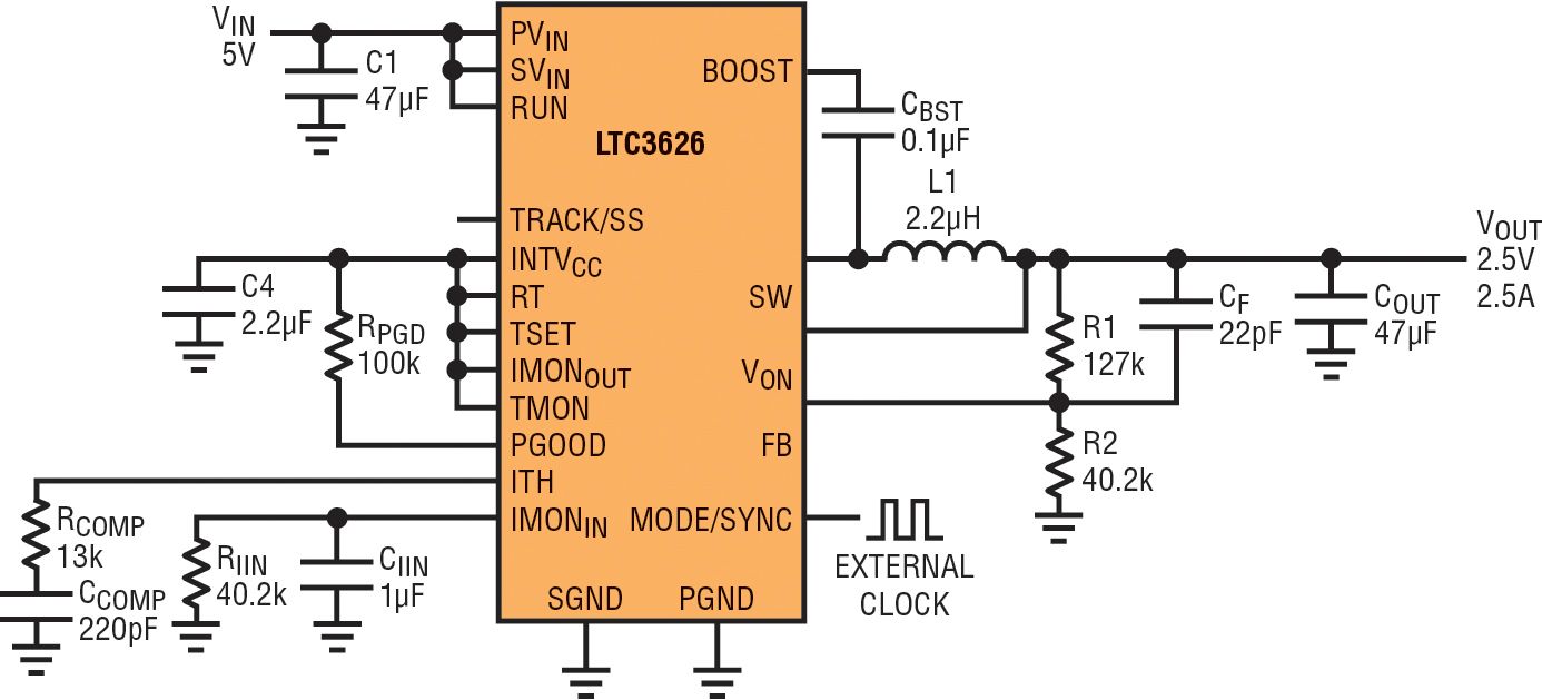
Figure 4. 5 V Input to 2.5 V output at 1 MHz synchronized frequency with input current monitor and 475 mA input current limit
Temperature monitor and limit
The device produces an estimate of the on-die temperature at the TMON pin. This feature can be used to determine the quality of the ground connection to the QFN exposed pad made during assembly. The exposed pad for the QFN is intended to provide a low impedance electrical connection to the board as well as good thermal contact. Visual inspection of this critical connection can be difficult, and a poor exposed pad connection may not be apparent by simple observation of the regulated output voltage even though the on-die temperature may be far too high for reliable, long-term part operation. Measurement of the TMON pin however gives the user insight into the exposed pad connection and hence the internal part operating environment.
As an example, Figure 5 shows data taken on two parts, one with a good exposed pad connection to the PCB, the other with a poor exposed pad connection. Though both parts regulate to the expected output voltage, it is clear from the internal temperature measurement that the internal operating environment is very different between the two parts. If placed in a system with an ambient operating temperature of say 70°C, the device with the poor exposed pad connection will clearly exceed the maximum allowed junction temperature of 125°C and will thus have compromised long-term reliability.

Figure 5. It is easy to determine the quality of the exposed pad connection by examining temperature measurements made by the LTC3626.
Conclusion
The continuous push for higher performance and power density faced by today’s system designers require small, flexible, and efficient point-of-load converters to maximize overall power chain efficiency. The LTC3626’s combination of wide input voltage range, output current capability, flexible feature set, and very small form factor make it ideal for many of today’s point-of-load regulator applications.
 If you enjoyed this article, you will like the following ones: don't miss them by subscribing to :